WPA2 – KRACK

As you are probably aware following the news this morning, a serious flaw has been found in WPA2 implementations on all devices/operating systems.

For further information on this, the white paper highlighting the flaw can be found here:

https://papers.mathyvanhoef.com/ccs2017.pdf

A synopsis on the problem here (good place to start):

https://www.krackattacks.com

And a higher level description by the Guardian Newspaper here:

https://theguardian.com/technology/2017/oct/16/wpa2-wifi-security-vulnerable-hacking-us-government-warns


pfSense and SNMP – Introduction

Introduction

It’s useful to be able to monitor devices on our network for a variety of reasons including security and performance issues. In this post we are going to provide a brief introduction on ow to do this. This post will form the foundation for future ones which dive into the subject further.

Our pfSense firewall supports the protocol known as SNMP (Simple Network Management Protocol) which allows us to do exactly that over a TCP/IP network. Many tools exist out there, but we will be experimenting with this one in particular since it is easy to install for learning purposes.

For those interested it operates at Layer 7 of the OSI-7 Layer model (the Application layer). A range of devices from servers to printers support the protocol and this list of devices also includes pfSense.

There are many use cases for SNMP.  If we build out our own server which acts as the management console for our home automation devices, it would be good to gather data on it and alert us if we need to administer it in some fashion. Or perhaps we wish to perform the same task on a firewall!

Each of these devices represent agents on our network.  Once we have the SNMP client software installed on the agent it will expose a set of variables to the management console which then allows us through these variables to update configuration and similar.

In this instance pfSense will act as the agent and will be administered by a management system running on a Linux based device.

For the purposes of this series of articles we will be using a simple Raspberry Pi 3 running Linux as an example of how to build out a management device and collection point for TRAPs.

Once you have the basics in place and are comfortable with how SNMP works you can roll it out to intelligent thermostats you may have built with the Raspberry Pi or similar devices.

To recap we therefore four components in this project:

  1. A Raspberry Pi – the manager
  2. The agent – the software running on pfSense
  3. pfSense firewall hardware -the managed device
  4. NMS (Network Management System) – the software component on the Raspberry Pi

Let’s take a quick look at the SNMP protocol before we start configuring our devices to familiarize ourselves with the features.

SNMP version 1.

Version 1 of the SNMP protocol introduced three important operations to interact with managed devices on an IP networks. These are GET, SET and TRAP

GET – This allows the management station to retrieve an object from an entity

SET – Allows the management station to SET objects on a managed entity

TRAP – Allows the entity to notify the management console of significant events.

SNMP version 1 also introduced the MIB. The Management Information Base contains configuration data and operational information. You’ll see a bit more about this later when we use a tool to walk through it, however here is an example of the data:

iso.3.6.1.2.1.1.1.0 = STRING: “pfSense pfSense.localdomain 2.3.2-RELEASE pfSense FreeBSD 10.3-RELEASE-p9 amd64”

Another important feature is the community name. Devices in the same community could authenticate with each other using this method.

There are a number of flaws in SNMP version 1. Security is very weak with the community name acting as a user group and password rolled into one.

In addition to this freshness checks e.g. nonce or timestamps are absent so replay attacks are possible and finally none of the data is encrypted.

SNMP version 2c.

SNMP version 2c  is almost identical to version 1, but has subsequently been superseded by SNMP version 3 which beefed up security relative to version 1. Version 2c added in the support for 64 Bit counters.

SNMP version 3.

In version 3 of the protocol we now have keys which are used to encrypt traffic from one device to another.  The device whose keys are used to provide auth/confidentially is known as the authoritative entity.

For GET/SET the receiver is the authoritative entity.

For TRAP the sender is the authoritative entity.

Another feature of SNMP version 3 is the SNMPEngineID which acts as a unique identifier for an entity on the network.

Those that’s a quick overview of the protocol. You can read more about here if you want to learn more.


Setting up the Raspberry Pi.

Our Raspberry Pi will eventually end up being our management console. However first we will install some basic tools on the device so we can monitor it from itself for learning purposes as well as review the MIB on the pfSense appliance.

Log in to your Raspberry Pi (or similar Debian based Linux device) and run the following commands:

sudo apt-get update
sudo apt-get install snmpd
sudo apt-get install snmp

Once the installation has finished we can edit the configuration file that contains the settings for SNMP on your device.

Using vim or a similar tool edit the snmpd.conf file e.g.

sudo vim /etc/snmp/snmpd.conf

Find and comment out the line with agentAddress and change it to the following:

agentAddress  udp:161

Then change the rocommunity to mysnmptext

rocommunity mysnmptest

Save the file and exit.

We now have our agent running on port 161 which is standard and using UDP (User Datagram Protocol).

Let’s now restart the services.

sudo service snmpd restart

We can check the process if running by running the following command:

ps -A | grep snmpd

You should see an output similar to the following

 2232 ?        00:00:00 snmpd

We can walk the MIB on the Raspberry Pi using a tool called snmpwalk.

To do this we need to run it using the community name (mysnmptest) then version (1) and the target machine (localhost).

Run the following command from you terminal:

snmpwalk -Of -c mysnmptest -v 1 localhost

You should now see some output similar to the following which is the OID and its value :

iso.3.6.1.2.1.1.1.0 = STRING: “Linux raspberrypi 3.18.7-v7+ #755 SMP PREEMPT Thu Feb 12 17:20:48 GMT 2015 armv7l”

The labels aren’t much help in defining what each of these output items mean in many cases. Therefore we are going to install the snmp-mibs-downloader library to resolve the OID to their text description.

From the command line run:

sudo apt-get install snmp-mibs-downloader

After this has completed, edit the conf file:

sudo vim /etc/snmp/snmp.conf 

We don’t need the mibs value, so go ahead and comment this out

#mibs

Save and exit the file.

Now let’s try rerunning the command again:

snmpwalk -Of -c mysnmptest -v 1 localhost

We should see the OID resolve to a string prefix now:

.iso.org.dod.internet.mgmt.mib-2.system.sysDescr.0 = STRING: Linux raspberrypi 3.18.7-v7+ #755 SMP PREEMPT Thu Feb 12 17:20:48 GMT 2015 armv7l

Here we can see the sysDescr i.e. System Description is the Raspberry Pi as expected.

Now we have tested this on the Raspberry Pi, let’s enable the option on pfSense.

Configuring pfSense

Enabling SNMP on pfSense is fairly straight forward.

You can access the SNMP settings through Services > SNMP

The following screen will be displayed

SNMP

First select the Enable option. This turns the daemon on.

Next in the System Location assign value e.g. “firewall”. Following this you can also add a System Contact e.g. yourself.

We are now going to change the Read Community String to mysnmptest which is what we assigned to community value on the Raspberry Pi.

Scroll down to the bottom option and set the Bind Interface to LAN. We only want this enabled on our local network, and certainly not the WAN.

Don’t worry about the other settings. We will re-visit the TRAP options in a later post.

Save the updates.

Testing our setup

We can use the tools we installed on the Raspberry Pi to query the pfSense box. return back to the command line and run the following:

snmpwalk -Of -c mysnmptest -v 1 192.168.1.1

This is the same as we did with the Raspberry Pi, however we have changed localhost to the be the IP of the firewall.

You should see a response similar to:

.iso.org.dod.internet.mgmt.mib-2.system.sysDescr.0 = STRING: pfSense pfSense.localdomain 2.3.2-RELEASE pfSense FreeBSD 10.3-RELEASE-p9 amd64

In this case the sysDescr is the pfSense firewall description.

So there we have it. SNMP clients setup in two locations and a method to review each devices MIB.

Conclusion

This post briefly introduced us to SNMP and installing it on the pfSense firewall and a secondary Raspberry Pi. We explored version 1 of the protocol. Future posts will cover how we can use this data for monitoring and more information on the OIDs.

In addition to this we will set up SNMP TRAPs and also look and SNMP version 3.

VPNs, firewalls and VLANs for Home Automation – Part 5: pfSense security features: TLS

Introduction

In this post we will be briefly looking at one of the security features available in pfSense – TLS. TLS stands for Transport Layer Security and is one of the building blocks of eCommerce. This will also introduce us to some other concepts such as X.509 certificates which will be useful when we setup a VPN.

TLS protocol

When you log into the pfSense web console you will see we use https in the URL bar. This is because we are connecting on port 443. The service used here is know as Transport Layer Security (TLS).

You will have seen this on eCommerce sites such as Amazon when you purchase goods and is denoted in the browser bar with a little padlock and the https protocol.

Within pfSense the option to set the web console to run over HTTPS (and thus use TLS) can be found on System > Advanced.

Here you will see a radio button selected labeling HTTPS. In addition to this a drop-down can be seen with SSL Certificate. Make a note of the name here as we will cover this later in the post.

TLS also known historically as SSL handles encryption and authentication. In pfSense it is used to provide a secure channel on which to connect to the web console in order to administer the firewall.

Currently when we visit the firewall via https we see an error:

TLS

This is related to the certificates that are used by TLS as part of the authentication process. We’ll look a little more into this error later in the article and how certificates are used as part of the security process.

The overall security services provided by TLS encompass:

  • Origin authentication – client to server at application and transport layer
  • Data integrity – to prevent being compromised in transport
  • Data confidentiality – to prevent eavesdropping

TLS is implemented using a key exchange mechanism, certificate verification and digital signatures. Typically the client authenticates the server and not the other way round – although mutual authentication is possible and supported by the protocol. As you can imagine this would be impractical/unnecessary on an eCommerce website with hundreds of thousands of users and where we would expect them to have their own signed key chain.

However there are arguably places where mutual authentication would be beneficial – such as online banking.

So how does TLS work? Let’s take a look at some of the gory details.

How TLS works

When a client connects to a server, it kicks of the TLS handshake. This process includes negotiating cipher suites, encrypting shared session keys and generating message authentication codes (MAC).

MAC in this instance defines a Message Authentication Code – a hashed version of  a message(s). It shouldn’t be confused with the MAC address on your NIC. So same acronym – different definition.

TLS also uses a key exchange service. This provides for key agreement which is typically achieved by the client sending a secret that has been asymmetrically encrypted to the server.

One of the current methods in TLS 1.2 of doing this is via RSA however this is being phased out in version 1.3. The Diffie-Hellman key exchange is also available in various forms. You can see a list of these formats here.

Let’s take a quick look at RSA as this method is used in a number of other tools we will be using such as SSH.

RSA

The RSA algorithm is made up of four steps, these being the key generation, key distribution/exchange and finally encryption and decryption. RSA is a type of “asymmetric”encryption methodology also known as public key encryption.

The key generation steps are designed to produce two keys; a public key and a private key. The public key can be distributed to multiple machines/users. The private key is kept secret. The methodology for this revolves around using large prime numbers and modular exponentiation.

With the key distribution step we can use RSA to allow us to transfer a symmetric encryption key via an asymmetric key exchange protocol. The public key can be distributed through non-secure channels and then used to encrypt said private session key. Only the owner of the private RSA key can subsequently decode this encrypted message containing the symmetric session key.

Symmetric encryption is generally faster than asymmetric encryption but relies on both parties having the same key. This isn’t practical in most cases or at least without having some form of key distribution mechanism. Examples of these mechanisms include Kerberos and other trusted third parties built around the Needham-Schroeder symmetric key protocol. Of course we can also use public key cryptography as a means of distributing a dynamically generated session key for symmetric encryption.

The fourth step has in essence been described above when discussing key exchanges. To encrypt a message the plaintext is encrypted using the public key and then sent to the other party.  They then use their private key to decrypt the message. The inverse is true. A message can be encrypted with the private key, and decoded with the public.

Many protocols use the public/private key only for setting up a secure channel. In fact after this has been completed we can expect the messages to be encrypted using the shared symmetric keys using the method previously described.

With a quick summary of RSA under our belt let’s take a look at the TLS handshake in more detail.

TLS Handshake

The handshake as we have discussed involves negotiating cipher suites, exchanging keys over RSA and generating MACs.

How this all fits together is demonstrated as follows with two roundtrips:

Client Server
Sends SYN
Sends SYN ACK
Sends ACK
Roundtrip 1. Sends ClientHello including TLS version, random numbers (32-bit nonce) and list of supported cipher suites
Roundtrip 1. Sends ServerHello with random numbers, Certificate and ServerHelloDone
Roundtrip 2. Confirms certificate is OK. Sends ClientKeyExchange, pre-master secret, ChangeCipherSpec,  and Finished message
 Roundtrip 2. ChangeCipherSpec, verify MAC and sends encrypted Finished message.
Decrypts Finish message with symmetric encryption key and checks MAC. Sends application data encrypted.
 Sends application data back and forth
 Sends application data back and forth until connection is closed.

One useful feature of the TLS handshake process is that part of it can be “re-used” across a session. This means if we navigate between multiple webpages, we can leverage the fact we have already completed the 2 round trips. Thus in this latter re-use case only a single roundtrip is used.

TLS components

Digging a little deeper into TLS we can see some of the components that make up the protocol and handshake we saw above.

SSL handshake SSL change cipher spec SSL alert Application data
Record protocol
TCP
IP

The first layer of the protocol contains the components needed for TLS handshake, alerting when the connection is closed and negotiating the cipher suite.

The next layer down is the Record protocol. This takes the data from the previous layer and fragments and encrypts it and also assigns an HMAC (Hashed Message Authentication Code).

Following this we see the TCP and IP layers.

If you would like to read more about how TLS works check out the High Performance Browser Networking guide by O’Reilly. This article includes more information on the handshake and other features of the protocol.

TLS summary

In the above section we have seen how TLS creates a secure channel between your machine and the pfSense box on port 443 to serve up the web console. We also mentioned that certificates are used, so what exactly is their purpose?

Certificates

Certificates are used to identify a party as trustworthy. This is important if you wish to transfer financial data between them and yourselves. They follow the X.509 standard where by a public key certificate chain (called public key infrastructure – PKI) is created. Each certificate is signed by a trusted party and ultimately by a trusted root authority. For example Google, Microsoft or a government department.

As you might imagine from the name, public key certificates are built around the same principles as public key cryptography.

When running the TLS protocol we check the certificate chain of the server to ensure it is trustworthy and the certificate hasn’t expire. If one of these two instances aren’t the case, we see an error same/similar to this:

Chrome cert error

In pfSense by default you will have a self signed certificate called “webConfigurator default”. You will remember this from when we looked at the Advanced screen. This is the certificate assigned to the pfSense box and used as part of the TLS authentication process.

To access the list of certificates on your system select System > Cert. Manager from the main menu.

This will bring you to the CAs tab. From here select Certificates.

On this screen you should see the certificate details and note that the Issuer (the CA) is self-signed. This is why we are seeing the error as the certificate is not signed by a trusted root.

As this is our local network we do not need to worry about purchasing a signed certificate. If you are interested in importing the self signed certificate however and trusting it in your browser – you can follow the steps here and also here for Mac users.

When we come to setup a VPN we will be creating a CA and also client and server certificates. More on this however in further posts.

Summary

In this post we briefly looked at TLS which explained the error we see when we login to pfSense web console. In addition it very briefly introduced us to RSA and X.509 certificates.

These topics will be covered in more detail in later posts. Next we will look at some further features in pfSense.

VPNs, firewalls and VLANs for Home Automation – Part 4: WAPs and security

Introduction

Now we have a small network up and running with WAPs and VLANs we are going to take a look at the security around these. One major concern has been that many home automation devices that are off the shelf rely on existing home networking technologies. If these are misconfigured or use weak encryption and passwords, then your home automation devices can quickly become a target. This is in addition to any flaws that may exist in the product itself.

Therefore this post will include:

  • Discuss some of the security issues around WAP including:
    • WEP
    • WPS
    • WPA/WPA2/WPA-TKS
  • MAC white lists

Let’s start with looking at wireless security.

Wireless security and our WAP

The 802.11b standard offers us two security services, those being Authentication and Encryption. Authentication is handled through shared key authentication and encryption through WEP.

As you will see WEP was a weak implementation and has later been replaced. You should not use WEP but the WPA2 option in your AP.

Shared Key Autherntication

When a device (known as a station) wishes to authenticate with a WAP a shared key is used. Initially however there is a process in place to communicate what the shared key will be.

WAP Device (station)
Send a random number to the station
Encrypt random number using RC4 with a 40-bit shared secret ket and a non-secret 24-bit Initialization Value (IV)
Send encrypted random number
Decrypt received message using RC4, 40-bit shared secret key and 24-bit IV
Compare decrypted random number to transmitted one
If the two numbers match, then both station and WAP use same shared key

So this is the basic steps for authenticating a user, however the traffic between the WAP and device also needs to be encrypted. The older and less secure mechanism for doing this was WEP (Wired Equivalence Privacy).

WEP – how it works and why you shouldn’t use it

WEP in a nutshell works as follows:

WAP Device (station)
Computes the ICV (integrity check vector). This is a 32-bit cyclic redundancy check
 Append to message to create the plaintext
Use RC4, 40-bit secret key with 24-bit IV to create 64-bit key
Encrypt plaintext using RC4 by XORing with a key stream of pseudo-random bits
IV is concatenated with the ciphertext
Cipher text and the IV are sent to the station
Cipher text and the IV are received by the device
RC4 algorithm uses a 40-bit secret key and 24-bit IV as 64-bit key
The cipher text is decrypted by RC4 by XORing with key stream of pseudo-random bits
 Separate ICV from message
 Compute ICV for message
 If received ICV matches the computed ICV then the message integrity is retained.

So looking at this, you may notice that only 40-bits of this key are truly secret – and you’d be right. This of course is a problem.

As we can see the IV is sent in the clear as it is concatenated with the cipher text. Calculating what the next IV is can also be a massive security issue as some NICs:

  • Use a pseudo-random IV – likelihood of the same IV being generated is very high in a shirt window due to only 24-bits being used
  • Use an ascending counter for each IV – at only 24-bits this will reset after a few hours
  • Use a combination of ascending/descending counter – same as above, eventually the sequence will reset

Thus by capturing two messages with identical IV’s an attacked can attempt to crack the encryption. This is due to the fact both messages while having a different plaintext have been created from the same IV and key.

XORing the two cipher texts results in: plaintext 1 XOR key stream XOR plaintext2 XOR key stream. However the key streams cancel each other out. The result of this is the plaintext’s XOR’d together. These can then be attacked via statistical methods to ascertain the two separate plain texts.

If this wasn’t problem enough our 40-bit encryption key can be weakened further by poor WEP key entry implementation in the WAP.

The root of this is that a user using a weak password/limited alphanumeric character set passphrase, shrinks the set of possible keys considerably. A passphrase will therefore only generate 21-bits of entropy – yes that means the key strength which could be 40-bits is now only 21-bits. And what of the remaining 19 bits – these unfortunately predictable.

Thus the number of passwords possible is somewhere in the region of 2 million. This may sound like a lot, but in fact can be brute forced in seconds.

Even a 40-bit WEP key is crackable within a few hours, so some companies are now using 128-bit keys (104-bit key and 24-bit IV) which an unfeasible to crack with current technologies.

It doesn’t end here though. WEP has two other known weaknesses such as weak keys leaking into the key stream and partially exposed keys allow the whole key to be determined (called the IV weakness).

If you wish to setup a a WAP for testing out the weakness of WEP, you can try a number of tools that will crack the encryption including: WEPCrack and Aircrack-ng.

WPS – Don’t use it

WPS standards for WiFi Protected Setup (protocol). Some AP’s contains a button you can press which and the request a connection from your station. Following this an 8 digit code is used to authenticate. 8 digits only allows for 11,000 possible combinations which can be cracked within 4 hours.

If your WAP has WPS disable it. if you can’t disable it, it might be time to buy a new device.

WPA, WPA2 and WPA-TKS

The WPA protocol/security certificate program is a replacement for WEP and was put in place to bridge the gap until the full 802.11i standard was rolled out.

WPA stands for  WiFi Protected Access. You will see WPA and WPA2 as common security options on modern WAPs, where it is encouraged to be used instead of WEP.  For example WPA replaced the flawed cyclic redundancy check was saw in WEP.

An extension to WPA was the Temporal Key Integrity Protocol. This was designed to allow WPA to accommodate older NICs that do not support WPA. Unfortunately it uses RC4 which introduced a weakness into the protocol. A weak PSK (Pre-Shared Key) passphrase can therefore be attacked by tools such as Cowpatty.

Typically you will see home WAP’s use WPA2-Personal aka WPA-PSK. For the moment will will use this, however later posts will provide the option to switch to WPA2-Enterprise mode.

Now is a good time to consider changing the SSID of your wireless network if you used a default one and also strengthening the password. For the WAP being used for Home Automation devices you should consider using an extremely strong passphrase. Typically you will only be registering devices with this WAP when you add them (as opposed to having guests etc. connect regularly/randomly).

Having looked at some of the security issues around wireless protocols we will now look at how we can use white lists on AP’s so in theory only certain devices can connect.

MAC whitelist (ACL)

A whitelist (access control list) is literally a list of devices permitted to connect to the AP. A device whose MAC is in the list is permitted to join the network, those who aren’t are blocked. Essentially you filter out devices who aren’t in the list by MAC.

Login to your second WAP and look for a white listing option if it exists. Once you understand how to add devices to the list, new Home Automation devices should be enabled here.

If you are using UniFI you may need a later copy of the controller to find this feature.

Of course this is not a full proof system. MAC spoofing would allow an unauthorized device, which has also cracked your WPA key to access the network. However it adds an extra hurdle.


Conclusion

In this post we covered the basics of WiFi protocols to get you thinking about security. As this series of posts progresses we will look at further methods of hardening our home automation network.

Also in later posts we will look at Kerberos as a tickets granting system and how 802.1x EAP protocol can be used with RADIUS.

In the next post we will return to pfSense and review the security at the firewall level.

VPNs, firewalls and VLANs for Home Automation – Part 3: Setting up the VLAN

Introduction

So far we have setup pfSense and connected up our WAP to it. This has formed the basics of our home network.

However it would be good if we could use multiple access points each running on their own network, but sharing the pfSense router, firewall and WAN. We also need to consider locking down the network to improve security.

In this post we will expand our network further to incorporate these items by:

  • Configuring VLANs in both pfSense and our VLAN compatible switch
  • Move our existing WAP to a VLAN.
  • Leave our LAN as Ethernet only with no AP attached

To start with we will do a little digging into how switches work to provide some context for when we later setup the VLANs.

Switches

A switch is a hardware tool (located at the Data Link Layer on the OSI-7 layer model) which is responsible for routing packets from one machine to another. A switch relies on knowledge of the networked machines MAC addresses.

Typically a hardware unit will consist of multiple Ethernet ports that devices can be plugged into. Our setup so far relies on using the WAP connected to a single Ethernet port to assign IP addresses to machines on the network. Once a machines has connected to the switch via the WAP, a record of its MAC/IP combo is stored on the pfSense appliance.

Switches were a replacement to what are known as Hubs (found at Layer 1 of OSI-7 Layer model). A Hub broadcasts messages out the whole network and any device connected to the Hub can read the packets. If a NIC was placed into promiscuous mode, then sniffing the packets and viewing the data was possible. A switch on the other hand only routes traffic to the target machine.

Of course this also mean your network speed is affected by the speed of the switch! A faster switch with the right Ethernet cable and newer NICs for the devices running on the network, improves overall speed.

If you cast your mind back to an earlier post you will remember we discussed the ARP protocol. One issue some switch configurations are susceptible to is what is known as ARP and IP spoofing.

Each machine on the network will keep a copy of the IP/MAC combo in their ARP cache. An attacker can therefore use its own copy of the ARP cache to try and eavesdrop on communications between machines.

The way this works is to send out a Gratuitous ARP message to the machines on the network and replace the portion of the MAC mapping, with the MAC of the attacker. The attackers machine then sits in the middle (man-in-the-middle) eavesdrops on incoming messages, and then forwards them on to the other party.

If you are interested in trying this out yourself then take a look at the dsniff tool.

At the switch level there is another issue we need to be aware of – MAC flooding.

The switch as you will remember contains a table mapping MAC’s to IPs. We can see this mapping in pfSense under the Diagnostics > ARP Table link.

A MAC flooding attack attempts to overwhelm the switch so that no new MAC/IP pairs can be generated (a DoS attack), or worst the switch reverts into acting like a hub, thus allowing eavesdropping.

Thankfully aspects of the 802.11 protocol defend against MAC flooding.  When a device associates with a WAP it is MAC-based.  Therefore the WAP bridges traffic coming only to/from known MACs.

Therefore if a MAC flooding attack is directed from a wireless device to the network, any 802.11 frames with a random MAC address in the source not associated with the WAP are discarded.

So now we have a little understanding of how switches work and some of the security considerations, let’s look at VLAN compatible switches.

VLAN Switches

For this portion of the post I will be referring to a Dell PowerConnect 2808 VLAN compatible switch. The 2800 series switches start at around $129.00 USD. If you are using a different device, then modify the instructions below as applicable.

VLAN stands for Virtual LAN. As it’s name may suggest, the concept behind it is to take one set of hardware i.e. ‘n’ machines and one switch and create multiple LANs from this. Each LAN being its own subnet. The traffic on each of these LANs is then tagged so we know which VLAN it belongs to.

pfSense allows us to configure VLAN interfaces and then assign DHCP servers to each of them. We therefore can use our VLAN switch as a method for connecting multiple AP’s (or wired devices) and let the configuration of the IP range etc. be handled by pfSense.

Configuring VLANs in pfSense

Our first task is going to be to move our WAP off the LAN interface on pfSense. Going forward we would like the LAN to only be accessible for devices connected directly to the switch.

We therefore need to come up with an IP range for WAP to use, since it will no longer using 192.168.1.0/24.

Let’s start by plugging out laptop/PC directly into the  pfSense appliance, as the WiFI will shortly stop working. You can also power down the WAP for the moment.

We are going to use the range 192.168.3.0/24 for our new VLAN.

Let’s start by navigating to Interfaces > (assign)

On the screen that pops up select the VLANs option. You’ll now be presented with a list of VLANs which currently will probably be none.

Select the Add button from the bottom right.

The VLAN Configuration screen will now be presented. On this screen we can create our new VLAN and tag it.

From the Parent interface drop-down, select the LAN option.

Below this you will see the VLAN Tag input field

VLAN Tag

Set this value to an integer between 1 and 4094. I like to use a value derived from the subnet. So if the subnet is 192.168.3.0/24 I use the tag 3. Do not enter the value 1 however. This will become apparent why later.

You can ignore VLAN Priority for now. If you wish to add a Description now is your chance. For example “HomeAutomation”.

Return back to the Interface Assignments screen under Interfaces. This will be updated with an Available network ports drop-down. Listed here you will see your VLAN.

Select it and click the green Add button. Once added you will see it has a name similar to ‘Opt7’

Next navigate to the Interfaces drop-down. Your new VLAN interface with the Opt7 (or whatever was auto generated) will now appear.

Select this option to go to the interfaces configuration.

Interface config

We have now going to select the Enable interface checkbox.

Following this change the Opt7 value to something more intuitive e.g. HomeAutomation.

The IPv4 Configuration Type should be changed to Static IPv4.

Our final task is to scroll down the screen to the Static IPv4 Configuration.

Change the value of IPv4 Address to 192.168.3.1 and ensure the ‘/’ value is set at 24.

Save these values.

Now navigate to the Interfaces > Interface Assignments screen. Here you should see the new Interface HomeAutomation (or whatever you called it) and the Network port should be similar to: VLAN 3 on igb1 – lan (HomeAutomation) .

We now have an Interface setup for our VLAN. This will work over our LAN connection allowing us to run a virtual LAN with the 192.168.3.0 subnet.

Currently our WAP is setup however to use 192.168.1.0/24 so we will need to change this.

First let’s get the DHCP server running on the VLAN interface.

Navigate to Services > DHCP Server from the list of available interfaces, select the one corresponding to your VLAN e.g. HomeAutomation.

When this screen loads you will see some General Options.

Here you will need to do the following:

  1. Check the Enable checkbox
  2. Select the Range e.g. 192.168.3.60 to 192.168.3.199

Save these changes.

Now we are finally ready to update that static mapping we created before for our AP.

So navigate to Status > DHCP leases.

Next edit the Static mapping you added for the WAP. Change the IP address to a new one in the new subnet 192.168.3.0/24.

Make a note of the IP address you selected, as we now need to update the WAP.

Save the changes.

You can now unplug the laptop from the pfSense appliance, unplug the WAP from the LAN port and power up the WAP again.

Once it is up, login to the web interface and change the IP address for the AP to the one you selected above.

So we now have a VLAN configured on pfSense and the WAP configured with an IP address for the new VLAN. That leaves us with our final task – setting up the VLAN switch so we can plug our WAP back in.

Configuring the VLAN switch

Our final task is going to be to configure the VLAN switch. As mentioned for this I have selected a Dell PowerConnect 2808, so you will need to tweak the following instructions to your specific switch.

First we are going to plug the VLAN switch from LAN port 1 into the Ethernet port where the WAP was originally, then power up the VLAN switch. Also plug your laptop/PC into one of the other free ports on the pfSense appliance.

Once it has booted up, the LAN DHCP server will assign it an IP address in the 192.168.1.0/24 subnet. You can check on the DHCP leases screen in pfSense to find out what was assigned to it.

Navigate to the web console for your switch and log in. Remember after you login to change the username and password from the default values to something more secure.

Once logged in we need to configure a VLAN for our HomeAutomation interface.

Within the GUI located the VLAN configuration screen. In the Dell PowerConnect this is:

Switch > VLAN > VLAN Membership

Under this screen we can select an existing VLAN or configure a new one. By default you should need a VLAN tagged with 1 available. This acts as a the Trunk, that all traffic is sent over and is the configuration associated with the Ethernet port (1), you plugged the pfSense appliance into.

The Dell switch comes preconfigured with the VLAN tagged as 1 and will not allow you to edit any of the details here. This configuration is needed in order for the switch to communicate with a router etc. once plugged in.

VLAN default

Use the Add button to load up the screen for configuring a new VLAN.

Add VLAN

Let’s enter the tag value we set in pfSense for the VLAN ID. I recommended using 3 earlier, but this can whichever value you chose.

For the name enter HomeAutomation, or whatever you decided upon when setting up the VLAN interface.

You can leave the final value as is and click the Apply Changes button.

Back on the VLAN Membership screen select the Show VLAN drop-down and select VLAN 3 (or whatever you chose).

You’ll see a small table now appear which is called Ports.

Clicking on a square will insert a character (this is on the Dell machine, other switches will have a different interface).

Select the square for port 3 (this is where we will plug the WAP into) and click it until a U appears. Port 1 should show a T, if it doesn’t click it until a T appears.

On other models of switches you will need set port 1 as the Trunk where the tagged data passes over, and associate the physical Ethernet port you will plug your WAP into with the VLAN.

Save/Apply these changes.

Our final task is going to be to update the Port settings. On the Dell PowerConnect 2808 switch these settings can be reached via Switch > VLAN > Port Settings.

Select the relevant Ethernet port, in our case 3. Make sure the PVID is tagged as 3 and finally make sure the Frame Type is Admit All.

Save these changes.

Our VLAN switched is now configured so that Ethernet port 3 can be used for the WAP and all traffic running over it through the Dell switch to pfSense will be on VLAN 3 with IP addresses assigned from 192.168.3.0/24 subnet.

Let’s now power everything down.

Hook the WAP to Ethernet port 3 on the VLAN switch. Next make sure that the VLAN switch Ethernet port 1 is connected to the LAN on the pfSense appliance.

Now let’s start everything up.

Once booted, connect your laptop/PC to the WiFi SSID and bingo you should now have an Internet connection.

If you log into pfSense and check the DHCP leases – your laptop/PC should appear in the list.

Next Steps – Add another WAP

To add a second WAP and VLAN to your network, repeat the steps above and this time use a VLAN tag of 4 (or other acceptable value from the range). Associate this VLAN with the 192.168.4.0/24 subnet and assign the WAP a static IP from this subnet.

You absolutely must assign a different VLAN tag and subnet for this to work. If you encounter problems with VLAN not working with the second WAP ensure that:

  1. DHCP is disabled on the WAP and configured correctly for your new AP in pfSense
  2. The VLAN is configured in pfSense
  3. The Interface is configured correctly in pfSense
  4. That the DHCP server is running on the new Interface with a different subnet to the other interfaces
  5. That the VLAN is configured correctly in the Dell switch
  6. That the port in the Dell switch is set with the correct tag
  7. That the device is connected to the correct Ethernet port

 Summary

In this post we hooked up our VLAN compatible switch. In addition to this, we connected up our existing WAP and saw how we could add a second one by following the steps for configuring the first.

We now have a home network with:

  • pfSense firewall appliance
  • A Dell (or similar) VLAN switch
  • Two wireless access points

In the next post we will look at the WAPs in a little more detail and discuss security.


VPNs, firewalls and VLANs for Home Automation – Part 2: Setting up the WLAN

Introduction

In this post we will look at adding a Wireless Access Point (WAP) to our pfSense box, and setting up a LAN (local area network). We’ll cover some theory on how LAN’s work including DHCP and ARP and also some background on wireless technologies associated with the 802.11 standard.

Let’s start with an introduction to LANs and how they are configured in pfSense to get a foundation.

LAN Networks

LAN stands for Local Area Network. A LAN is essentially all the devices connected to our home network, sitting behind the firewall/switch combo (sometimes called an appliance) and which are assigned an IP by the DHCP server in it.

Our current setup consists of the pfSense box and the laptop/PC we connected to it for configuring access to the Internet.

Within the pfSense box is some software known as a DHCP (Dynamic Host Configuration Protocol) server. This is responsible for handing out IP addresses to the machines that connect to the Ethernet network.

We’ll dig into each of these technology in more detail now.

Ethernet

The cables that plug into your PC and pfSense box are known as Ethernet cables.

Ethernet is a standard and family of technologies used for creating networks such as the LAN in your home. Over the years the technology has evolved from using 10BASE5 coax cable (similar to a cable TV provider uses) to the Cat5 and Cat6 family of cables (Cat7 now being available and currently Cat8 is being developed) .

Cat6 cables are the newer of the two technologies we are interested in and supports up to 10-Gigabit Ethernet (10GBASE-T). Cat5/Cat5e which are also commonly found support speeds of 100Mps and 1000Mps.

Depending on what your network hardware supports you can choose the corresponding cable for maximizing speed. In all likelihood you will have an Ethernet cable as provided with your ISPs modem. This you can use to hook up your pfSense appliance to the modem.

As we saw in the previous post our TCP/IP protocol stack has 5 layers. The Network layer of this stack is where Ethernet can be found. At this layer the IP datagram is packaged up as an Ethernet frame.  At this point something called a MAC address is inserted into the header and the frame is passed to our network card (NIC) for transmission across the cabling (Cat5e, Cat6 etc.).

We’ll be covering a bit more about the MAC address next when we look at the DHCP server and ARP.

DHCP Server

On your pfSense box there is a service running called DHCP (Dynamic Host Configuration Protocol). You can access this from the main menu:

Main menu

Under the Services drop-down. Here you will find an option called DHCP Server.

Click on this link. You should now see the DHCP server options for your LAN.

DHCP

In the above screen shot we can see the DHCP server is enabled, this means that new machines connecting to the LAN will be dynamically assigned an IP address.

We can see next two values, those being the Subnet and the Subnet mask.

The Subnet(work) designates the subdivision of the network that our IP’s will be issued on. Using CIDR (Classless Inter-Domain Routing) notation we can specify the IP address assigned as the prefix, and then the range of IP’s available as hosts.

So for example 192.168.1.0/24 would be the CIDR notation of our current network. What this means in simple term is that all the IP’s will be prefixed with the 24 bits (192.168.1.0) and the hosts will be available in the remaining 8 bits (1 – 254). For example 192.168.1.10.

The value below this is called the Subnet mask. This is just another way of representing the /24 value.

When 255.255.255.0 is bitwise ‘AND’ with the IP address we get the routing prefix (192.168.1.0).

If you wish to change these values to a valid private IP address range you can use the subnet calculator to work out the values.

The final two fields tell us the range of IP’s we can allocate to hosts, and the selected range. For example we can allocate IP’s between 192.168.1.1 and 192.168.1.254, however for demonstration purposes I have set the range to only be between 192.168.1.100 and 192.168.1.199.

Therefore devices will only be allocated IP address dynamically between these two values.

If you have made changes to the values here, save them.

So what happens if we want to see which IP addresses are currently in use, and thus which machines on our network have an IP allocated to them?

Well pfSense provides a handy option under the Status > DHCP leases link.

This status report shows:

  1. IP address – The IP address assigned to your device e.g. 192.168.1.7
  2. MAC address – This is the hardware address of your device
  3. Hostname – Some devices will have a hostname configured e.g. raspberrypi or EvesMacBook
  4. Description – provides a description of the device if it exists
  5. Start – The start time and date of the DHCP lease
  6. End – The end time of the DHCP lease
  7. Online – Whether the device is online or not
  8. Lease type – If assigned by the DHCP server this will be active. If you assigned a static IP this will be static. More on this later!

So when a machine connects to the switch running pfSense, how does the DHCP server know how to assign an IP address and route packets to it?

That’s where the MAC address and ARP come in.

MAC address and ARP

The MAC (Media Access Control) is a unique 48 bit address assigned to your Network Interface Card (NIC) by the manufacturer. It will be in the format AB:CD:EF:12:34:56

The NIC operates at the Data Link Layer of the protocol stack and acts as an address on both wired and WiFI networks. Earlier we noted that the MAC address is inserted into the header of the Ethernet frame.

You’ll notice on the DHCP status page, your IP address is linked to your network cards MAC. How exactly does this work though? This is where ARP (Address Resolution Protocol) comes into play.

In pfSense click the Diagnostics drop-down and then select the ARP Table link.

You’ll the see screen presented shows similar information to that on the DHCP leases page.

The ARP protocol works by taking the IP address and translating it into the MAC. This allows for traffic to then be passed to the device in question.

First however a machine needs to register with the DHCP server to have a suitable IP addressed assigned to its MAC. It announces itself to the switch by sending a Discovery request.  This request is sent out to the network at the IP layer with a destination IP address of 255.255.255.255 and with a source IP address of 0.0.0.0.

This request of course is packaged up as an Ethernet frame, so a source MAC is included with a network broadcast destination of FF:FF:FF:FF:FF:FF – (in essence this will be the same location as where the DHCP server is listening).  Once the DHCP server receives the IP portion of the request, it will respond to the source MAC with an offer packet wrapped in an Ethernet frame.

Following this your machine requests a lease from the DHCP server, and subsequently the DHCP server acknowledges the release. Your machine is now associated with an IP address in the ARP table of the switch.

Thus other machines can send packets to the switch, which will in turn route them to your machine via the IP/MAC association.

When a client of the network wishes to update the ARP cache of other systems it sends out what is called a gratuitous ARP request. In this case both the source and destination IP address are that of the client. However the frame is send to the broadcast address, which you will remember is FF:FF:FF:FF:FF:FF. Thus the Ethernet frame is sent to all ports on the switch (pfSense in our case). No reply is expected however, and this is a useful feature.

Gratuitous ARP requests are handy for example when we wish to announce that a MAC address has moved physical ports on a switch. They can also help to debug IP collision conflicts. If a reply is received, then we know two devices are trying to use the same IP (for example two machines may have had their configuration hard coded to use the same IP address).

There are also some security risks inherent in Gratuitous ARP requests which will be looked at in later posts.

So this is a simplified overview if how your machine is assigned an IP address so it can communicate with other devices on the network.

Next we are going to hook up a Wireless Access Point so that we don’t have to rely upon the limited number of physical ports on our router.

Wireless Access Points (WAP)

A key component of an 802.11 wireless network (WLAN) is the access point (AP/WAP). The 802.11 standard supports two modes of operation. The first of these is known as infrastructure mode.

In this mode the network has at least one AP plus the clients that associate with it. This combination of clients and the AP is known as a Basic Service Set (BSS). It’s possible for us to have more than one AP runnings on the same WLAN. This can provide greater coverage for example. When we use more than one AP to create a single subnet, this is known as an Extended Service Set (ESS).

For the moment we will be dealing with the simpler of the two cases – the Basic Service Set.

The second mode, which we will not be dealing with in this post is Ad-hoc (aka peer-to-peer) mode. This allows for impromptu collections of wireless devices to communication with each other without using an AP. Typically this would be used if there was no need for these devices to require an onward connection to the Internet or local LAN. This set of devices is known as an Independent Basic Service Set (IBSS).

A wireless access point can also act as a DHCP server, handing out IP addresses like we saw with the pfSense appliance above or leverage the DHCP server running on pfSense itself.

For this tutorial we have going to use the DHCP server on pfSense. Later as we integrate VLANs into our home network it will become apparent why we wish to use pfSense offerings, rather than any built in features on our WAP.

My preferred brand of WiFi router/AP is Ubiquiti UniFI. In addition to AP’s they make a range of network gear that is perfect for home use.

Things to consider in an AP are the range. Typically you want to be within 100 meters of the AP. Antenna types also make a difference, with directional and omni directional devices being available. Those that are omni-directional should be placed towards the centre of the building.  Later in this series of posts we will consider some of the risks associated with the WAP and range.

Many readers may want to repurpose old WAPs they have or may have done this already if they followed my article Raspberry Pi powered TV and dd-wrt router configuration.

If you go this route and are new to open source router software you may be interested in replacing the firmware with dd-wrt. At the dd-wrt website you will be able to find a list of router/AP models supported. This software unlocks many of the features on your AP that are often hidden by default firmware offered by the manufacturer.

Once you have AP ready, we are going to power it up. Don’t connect it to your pfSense switch just yet however.

Users of the UniFI will probably need to download the UniFI controller in order to administer their WAP. You can read me about the software and options here.

By default many WAPs will use an IP address in the 192.168.1.0 subnet. This will collide with the IP addresses issued by the DHCP server on pfSense (this is an example where the Gratuitous ARP request may see a reply).

We therefore need to disable the DHCP server on the AP before we can plug it into pfSense.

Your powered up WAP should now be broadcasting its SSID (Service Set ID), which will be visible on your machines list of wireless networks. The SSID is the informal name that you have applied to your network e.g. MyHomeLAN.

Each AP regularly broadcasts a beacon which acts as an advert for the AP and contains information about the service set and the amount of noise on the channel the AP broadcasts on.

Select the SSID and connect. Note if there is a password you need to apply this to connect. We’ll touch a bit more on passwords later when we configure the AP.

Next navigate to the IP address the WAPs web administration page runs on.

For example this may be : 192.168.1.1

Login into the web console using the default credentials. If you don’t know these, you can normally find them via Google. For dd-wrt users, check here. After you login, make sure to change the password from the default one, to something stronger.

For UniFI users, you will be able to connect to an associated AP via the controller.

Once logged in we will want to disable the DHCP server on the AP.  The following guide provides comprehensive steps for this on dd-wrt:

https://www.dd-wrt.com/wiki/index.php/Wireless_Access_Point#Turn_Off_DHCP

The short universal version of this is for all WAPs is:

  1. Set the Local IP address to a valid IP from the range you configured in pfSense – for example 192.168.1.101. We are going to set this as a static IP pfSense.
  2. Set the subnet mask to be 255.255.255.0 – this is the same as we set in pfSense
  3. Disable the DHCP server. You may also need disable DNSmasq if it is enabled
  4. Set the Gateway to that of your router.

Save the changes. We can now power down the WAP and plug it into pfSense. Make sure you chose the LAN port and not WAN/Internet (which should be connected to your ISP modem). You can now power up the AP again.

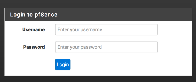
You should now see that your laptop/PC is assigned an IP address in the 192.168.1.0/24 subnet. Going to 192.168.1.1 should present you with the pfSense login screen.

Go right ahead and login.

Your WAP now has an IP addressed assigned to it by the DHCP server. If you check the DHCP leases page, it should be the IP that was explicitly set in the AP when you configured it.

We can configure this static mapping in pfSense as well. Next to the entry for your WAP should be a small white button with a blue cross in it. Hovering over this will reveal the label “Add static mapping”.

Click this button and the Edit Static Mapping page will appear.

On this screen we are interested the following:

  • MAC Address – The value here should be preset with your AP MAC
  • IP Address – This should be pre-filled with the value from your AP
  • Hostname – If one was assigned by your AP it will appear here
  • Description – Feel free to add a brief description of what this device is e.g. WAP for LAN

After adding the Description Save you changes.

As with an 802.3 Ethernet device such as your laptop’s NIC, the AP has a 48-bit MAC address as we saw above. The AP’s MAC is also used as the BSSID i.e. Basic Service Set ID. This is the non-user friendly ID of the wireless network you mapped the SSID name to.

The MAC (located in the Data Link Layer) for your wireless devices cannot leverage something called CSMA/CD which is used by wired Ethernet. CSMA/CD stands for Carrier-Sense Multiple Access with Collision Detection.

CSMA/CD basically senses if there is traffic on the wire and uses a process (including a waiting period) to decide when to attempt to send/resend a packet.

Our AP and wireless devices thus use a variation on this technique called CSMA/CA where CA stands for collision avoidance.  We can aid the quality of our wireless network therefore by choosing which channel our AP broadcasts on and thus reduce the chances of a collision.

Open another tab in your browser or the controller for UniFI. For example http://192.168.1.101

Once logged in navigate to the options where you can set the AP channel. You may have to explore the menus to find this. Regardless if you are using dd-wrt or not, their website provides a handy guide to how channels work here.

The following site lists tools and techniques for checking what the WAP’s near you are using with regards to channels. We are going to use a tool like this to find a potentially less busy channel to run our WiFI connection over.

If you are using a Mac, this scanning tool is built in. Holding down the Option key and clicking the WiFi icon, will display a menu option called Open Wireless Diagnostics.

You can ignore the Wizard that appears and then from the Wireless Diagnostics menu that is displayed at the top of the screen select Window > Scan.

This will bring up a window with a list of Networks, BSSID’s Security protocols, Wireless Protocol i.e. 802.11a/n or 801.11b/g/n etc. RSSI, Noise, Channel, Band, Width and Country.

If you are using a third party tool on Windows or Linux, load it up and explore which channels are less used.

For 2.4 GHz WiFi channels 1, 6 and 11 are the most commonly used as these channels do not overlap with each other.

Based upon this you can choose a channel for your AP to run over that is unlikely to experience as much noise.

Once/if you change the channel, save the changes and reboot your AP.

You should now be able to hook devices up to the AP and receive and IP and Internet connection via pfSense. If you want to check which devices are now using the AP, remember you can always look at the DHCP leases status in pfSense.

Wrapping up

In this blog post we saw how to:

  • Hook up a wireless access point to pfSense,
  • Configure the WAP to use a static IP
  • Disable the WAP DHCP server so pfSense assigns the IP address to clients
  • Change the channel on the WAP
  • Learned a little bit of theory around 802.11, ARP and MAC addresses

Now we have the basics in place we can explore setting up VLANs and thus segment our home network in order to group devices.

For the next article you will need a VLAN compatible switch such as a PowerConnect 2808 and another WAP.

VPNs, firewalls and VLANs for Home Automation – Part 1

Introduction

In this post we will be setting up the pfSense firewall and disabling the features on our cable companies modem/router combo.

Before we start with the pfSense install however, we will quickly cover a little bit of theory on the OSI-7 Layer model and TCP/IP model. Following this we will examine what firewalls are then apply this knowledge to pfSense.

This background information will help when coming to understand how the firewall, VPN and TLS work together in later posts.

Let’s start with a (very) brief overview of the OSI and TCP/IP protocol stack.

OSI-7 Layer and TCP/IP protocol stacks

Fundamental to how networks work is the idea of the OSI-7 Layer and TCP/IP protocol stacks.

Both of these stacks essentially describe the same thing: the creation of packets of data that are sent across a network between machines to allow for communication.

The OSI-7-Layer representation is as follows:

7. Application – Here we find application level protocols such as HTTP
6. Presentation – Concerned with both how data is represented/encoded and transferring data in a  language or syntax that the receiving machine can understand. The encoding technique is covered by Abstract Syntax Notation (ASN).
5. Session – This layer handle the sessions between machines for tasks such as file transfer. Within this layer there are two main services:

  1. Dialogue control and token management
  2. Synchronization
4. Transport – At the Transport layer data is passed into it from the Session layer and is divided into smaller units and then passed to the next layer (Network layer). At this layer the type of service that will be provided is decided, for example:

  1. An error-free, point-to-point channel
  2. Transportation of messages with no guarantee of ordering
  3. Broadcasting messages to multiple destinations


3. Network – The Network layer provides a uniform addressing scheme for network addresses and also provides two services, these being:

  1. Connection orientated : provides end-to-end connections that are reliable
  2. Connectionless : provides packet sending service with no-confirmation that it reaches the destination
2. Datalink – Used for providing error-free transmission service for data.  Data is handled as frames.
1. Physical – This is the lowest level of the stack and handles how data is transferred from binary format into voltage over the line.

Each layer of the stack offers services to those above (Layer N + 1), these are accessed at the service access point (SAP).

Data is passed down the stack via SDU’s (Service Data Units) which encapsulate a PDU. A PDU (protocol data unit) is a virtual unit of communication between two machines. These contain information such as headers and sequence numbers.  Thus the PDU is passed to the corresponding layer of the stack on the counterpart machine.

Note: A PDU at each layer of the stack may be known by an acronym such as APDU (application Data Unit).

The Internet (TCP/IP) model was an alternative model proposed to that of the OSI-7 layer. It’s geared towards TCP/IP protocols (as the name suggests) which underpin the Internet.

TCP standard for: Transmission Control Protocol.

This model is demonstrated below, as you can see it is simpler and some of the layers overlap either directly or in part with the OSI-7 layer model:

Application – Corresponds to the OSI Application, Presentation and Session layer
TCP – This layer corresponds to the Transport layer. Here we find the TCP segment.
IP (Internet) – The Internet layer matches sections of the Network layer. Here we find IP packets.
Network – This layer overlaps with the Network layer and encompasses the Data link layer
Hardware – This matches the Physical layer in the OSI model

TCP/IP relies on two important packet types, those being:

  • TCP – a connection orientated protocol. Its protocol units are known as segments
  • UDP – a connectionless orientated protocol. Its protocol units are called datagrams

As with the OSI-7 layer model PDU’s (known as segments) are passed down the protocol layers in SDU’s at SAP’s. Finally they are converted into voltage, sent out onto the wire, and the reverse process happens at the other end.

When dealing with firewalls there are some important things we need to know about some of the above layers of the TCP/IP model and the data sent back and forth.

Namely:

  • The IP layer is concerned with the IP address information contained in the IP datagram. The IP address being a numeric identifier of a machine.
  • The TCP layer is concerned with the port information contained in the datagram/segment. The port number is a numeric value detailing where a software service is running.

When we examine data coming in and out of the firewall these two pieces of information will become important in deciding what rules we wish to configure. In addition to this the type of packet will also come into play (for example UDP versus TCP).

You may find that referring back to these helps when we discuss aspects of how a firewall works next.

Firewalls an overview

Firewalls are responsible for filtering traffic in and out of a network. Generally speaking there are four types of firewall, these being:

  • Packet filtering firewalls
  • Circuit-level proxies
  • Stateful packet filters
  • Application-level proxies

In addition to this we have two special case firewalls:

  • Web Application Firewalls (WAF)
  • Personal Firewalls

Stateless packet filtering firewalls

A packet filtering firewall will look at incoming/outgoing packets that a router wishes to route to a destination machine, and decide whether to block the packet or not. This blocking could take the form of disregarding the packet, or responding to the sender with a notification of failure.

The criteria it will typically use to block a packet include source/destination IP and source/destination port number. This criteria is controlled by a rule set. You’ll see in pfSense later (which is in fact a stateful firewall) how we can configure a rule set.

Rules in this type of firewall need to be configured for both client to server and server to client, which can be fairly onerous to manage.

As we saw above the port number and IP address are contained within our TCP/IP packet. Thus a packet may contain a valid IP address at the IP layer, but the port specified at the TCP layer is blocked.

Circuit-level proxies

A circuit-level proxies firewall works in a slightly different fashion to the packet filtering firewall.

Rather than filter and route packets to machines on the network, it in fact takes the incoming packet and re-creates it if valid against the firewall ruleset. Thus the firewall acts as a proxy, taking incoming and outgoing packets, examining the contents and recreating and sending if valid.

This adds an important security aspect to the firewall. The packets being sent to and forth from the firewall will thus only contain information about the firewall. This is rather than that of the system that sent the original packet e.g. your local Linux machine. Thus the firewall obfuscates information that may be used to construct attack vectors by a malicious party.


Stateful packet filters

The next type of firewall is the stateful type and pfSense falls into this category. Stateful firewalls are one of the most common types found today and provide a good compromise on performance, ease of use and security.

A stateful firewall allows you to configure a single rule such that reply packets from a server to client are handled by the same rule as the client to server. Ancillary packets related to the connection can also be recognized by the rule without the need to configure further rules.

Thus a single firewall rule for connections can handle reply packets, and the nuances tailored at the client-to-server rule level. When a connection ends between the client-and-server further communication via the path is blocked as the state of the connection is closed.

This will all become clearer when we configure pfSense.

Application-level proxies

As the name may suggest the Application level proxy firewall, is concerned with filtering traffic at the Application layer. In addition to this, it checks the port number of the destination packet is associated with the application.

As the with the circle level proxy, the packet is not routed, but re-created. However there is one very big difference that should be explained.

The application level proxy firewall contains a complete representation of the OSI-7 layer protocol in both client and server form (rather than just server form) for each supported protocol.

Thus to support voice, email, HTTP, video etc. a model of each needs to be present within the firewall software. This allows far more granular security and allows the application to block certain aspects of a supported protocol.

For example if we wish to only support HTTP POST requests at the firewall level, we can block DELETE, GET, PUT etc.

For a home network this may be overkill, however it could be argued for a subnetwork consisting only of IoT devices this may be incredibly useful, if requiring a large overhead to maintain.

Next we will briefly touch upon our two special case firewalls.

Web Application Firewalls (WAF)

Web Application Firewalls are a software based service that allows us to filter out traffic that may be considered harmful., This could be DoS style attacks that attempts to SYN flood a network, SQL injection attacks, XSS attacks or similar attempts to compromise a website/network.

While not directly applicable to what we are concerned with in our home IoT network, they are never-the-less interesting to understand.

You can read more about them at the OWASP website.

Personal Firewalls

Last but not least is the personal firewall. You may be familiar with this type of software as it can be found in operating systems such as Windows. It’s designed to protect a single machine, especially in the past those that connected directly to the Internet via dial-up.

Now we have quickly run through the firewall types available and a bit about the networking protocols around them, let’s take a look at pfSense.

pfSense – An Introduction

The pfSense firewall is an open-source application wth many of the features found in (expensive) commercial firewall products. It is built on-top of the FreeBSD operating system.

The current version 2.4 includes:

Many of these terms may be new to you, but those that are important will be covered over the series of posts.

For those interested a pre-installed version of the software can be found bundled with Netgate’s custom firewall hardware.

If using an existing hardware option then pfSense can be downloaded directly from the pfSense website here. They also provide a handy guide to building/purchasing hardware specifically to support pfSense.

Once your hardware has been selected, follow the installation guide located at the pfSense wiki.

As per the wiki once installation is complete, the following default configuration options are in place:

  • WAN is configured as an IPv4 DHCP client
  • WAN is configured as an IPv6 DHCP client and will request a prefix delegation
  • LAN is configured with a static IPv4 address of 192.168.1.1/24
  • LAN is configured to use a delegated IPv6 address/prefix obtained by WAN (Track IPv6) if one is available
  • All incoming connections to WAN are blocked
  • All outgoing connections from LAN are allowed
  • NAT is performed on IPv4 traffic leaving WAN from the LAN subnet
  • The firewall will act as an IPv4 DHCP Server
  • The firewall will act as an IPv6 DHCPv6 Server if a prefix delegation was obtained on WAN, and also enables SLAAC
  • The DNS Resolver is enabled so the firewall can accept and respond to DNS queries
  • SSH is disabled.
  • WebGUI is running on port 443 using HTTPS
  • Default credentials are set to a username of admin with password pfsense

Our next step is going to be to connect pfSense up to our ISP via the modem/router combination. When we do this, we will disable the routing options on the device so that pfSense can handle our LAN.

What this will mean is that:

  1. Traffic will pass through the ISP modem un-filtered (some traffic filtering may happen at the ISP level however prior to reaching your device)
  2. pfSense will act as the firewall for filtering traffic
  3. The DHCP server in the ISP cable modem/router combo will no longer be responsible for handing out IP addresses to machines on your network.

For those of you who own your own device and do not use the ISP’s you should set your router and/or modem up to pass traffic directly through to pfSense.

This is typically known as Bridging and router/modem combos often have a Bridge Mode. This mode transparently links two networks: the ISP and your home network.

Googling your modem/router combo should provide you with instructions on how to switch it to Bridge Mode.

Disabling routing in the modem/router combo also avoids a problem known as Double NAT (Network Address Translation).

Double NAT

The NAT service effectively translates traffic from your external IP (provided by the ISP) to the internal IP address assigned to the router.

In the case of double NAT, the external IP assigned by the ISP has to be translated into the modem/router combo’s internal IP that is assigned to your secondary router. Then once again translated from this internal IP address (assigned to your secondary router) to the internal IP address of said router.

This doubling up is a bid of a headache and redundant to boot.

Connecting to the firewall to the modem

The following stage of our setup will see Internet connections on your home network interrupted until setup is complete. For these steps you will need an ethernet port on your laptop/desktop. Newer Mac’s such as those with USB C only ports do not include this by default, so a Ethernet dongle is a useful addition to your toolkit.

What we are going to do is connect the modem in Bridge Mode to the pfSense firewall. This will direct all web-traffic through to the firewall.

Following this, we will configure the firewall to act as a DHCP server.

The DHCP server (Dynamic Host Configuration Protocol) is responsible for assigning IP addresses within a set range to machines that connect to the firewall LAN (Local Area Network). We will see in later posts how Wireless Access Points (WAPs) can leverage this feature, as well as VLANs.

To get our initial setup, up and running complete the following steps:

  1. Connect your modem to the pfSense hardware device. Both devices should be powered off.
  2. Connect an ethernet cable from the WAN port on the pfSense device to the LAN port of the modem.
  3. Next attach your laptop or desktop device to the LAN port of the pfSense device via ethernet.
  4. Power all of the devices on and give them a few moments to boot up.
  5. With your attached machine, navigate to the following IP address in a browser: https://192.168.1.1 – This is the default IP address that pfSense uses.

Depending on your browser you should expect to see an error message similar to the following (Chrome browser):

Chrome cert error

This is due to the fact we are trying to access the Web console over HTTPS (SSL/TLS) connection and the certificate authority is considered invalid.

We’ll cover more on TLS in later posts and how this protocol works.

Click Advanced (or similar depending on browser) and then Proceed to 192.168.1.1 (unsafe).

You will now be presented with the pfSense web console login.

pfSense login

By the default the password and username are:

  • username of admin
  • password of pfsense

Once logged in the pfSense dashboard will be presented. Along the top of the screen is the menu that provides short cuts to the major sections of the firewall:

Main menu

On the right hand side of the screen you will see in the top right a list of interfaces.

Interfaces panel

Next to this is the ISP IP address of the WAN and LAN with the pfSense devices IP.

Our first task once logged in is going to be update the password of the admin account.

Change admin password

From the System menu:

System menu

Select User Manager.

On the screen presented you will see the admin user account. From this screen select the pencil icon next to the admin user.

You will be presented with a screen allowing you to edit the user details. Change the password for the admin on this screen, then use the blue Save button at the bottom of the page to update the changes.

Now logout of pfSense using the icon in the top right:

Logout

From the login screen, log back in.

Next let’s take a look at the firewall rules.

Basic firewall rules

By default we want to allow Internet traffic in and out of the firewall. You should find by default the firewall is configured to allow all IPv4 TCP and UDP traffic to and from the LAN.

You can test this by trying to access Google or a similar website.

We can check that the rule is indeed enabled, by going to Firewall > Rules from the menu at the top of the pfSense screen.

Select the LAN tab from the list presented. On the screen that loads you should see the following rule:

LAN rule

If for some reason the rule is missing, we can add the rule as follows.

Adding a rule – quick guide

To add a new rule click one of the Green Add buttons (there are two to choose from, and these simply add the rule above or below an existing one, so either will suffice):

Add up or down

On the screen presented we now need to update the following input fields under Edit Firewall Rules:

  • Action should be set to pass
  • Interface to LAN
  • Address family to IPv4
  • Protocol to any

The following screen shot demonstrates what this looks like:

Screen Shot 2017-04-22 at 3.32.57 PM.png

Next we need to make sure under the Source section the value is set to LAN net and under Destination the value is set to any.

The following screen shot demonstrates how the rest of the settings should look:

Source destination and extra

Save the changes.

You will be returned to the firewall rules, and will see the following message:

Screen Shot 2017-04-22 at 3.37.52 PM.png

Click the Apply Changes button to update the firewall. Once complete you should see a message showing they have been successfully applied.

You should now be able to access the Internet.

In future posts we will look at the rules set in further detail.

Summary

So far we have setup our modem in Bridge Mode and directed traffic to our pfSense firewall. The firewall is now configured to allow traffic to and from the Internet for devices plugged directly into it.

Next in VPNs, firewalls and VLANs for Home Automation – Part 2 we will look at configuring a WAP to allow wireless access for multiple devices to the web. Here we will look at DHCP and ARP in more detail.

In later posts we will convert the WAP over to using a VLAN.


VPNs, firewalls and VLANs for Home Automation – Introduction

Introduction

There are now a plethora of products on the market for home automation from wireless power outlets to intelligent thermostats. The typical user experience is to plug the device in, hook it up and connect it to either your local WLAN/LAN.

Many of the commercial products also allow you to access the device remotely and  configure it over the Internet. In addition to this they may provide a site you can log into to view stats, live camera feeds etc.

This is all well and good, but there are some serious security and privacy concerns here. Not least of which is the sharing of data with 3rd party services that can be then re-sold to advertisers.

In addition to this privacy concerns around allowing your ISP to view internal cameras, or the risk of devices being hacked either at the ISP or home level have added more variables to the mix.

In this series of articles we will look at how you can configure your home to use a VPN for remote access, setup a firewall and use VLANs for segmenting your home network. This combination of technologies will give you the ability to then build out your home automation services without relying on 3rd party websites to control and monitor them from afar.

In addition to this, with the right choice of commercial or home brewed devices you can protect against data being shared beyond your own home network.

Over the course of this series of articles we will look at:

  • Setting up a firewall and disabling your ISPs firewall service/replacing their router/modem combo with an off the shelf one.
  • Installing a VLAN compatible switch and configuring a VLAN
  • Setting up multiple AP’s for your VLAN
  • Configuring OpenVPN to access your home network remotely.

Throughout the articles we will cover a variety of topics related to each of the above. This will include the Diffie-Hellamn key exchange, IPSEC, Tunnel and Transport mode, VLAN tagging and Certificate generation.

For those interested in following along with these articles, the following hardware and software is used. The hardware can be switched out for any other equipment that meets the same needs.

In Part 1 we will start our adventure by setting up the pfsense firewall and disabling the cable company/ISP’s offering.