Project updates

Things have been a little quiet as of late due to me being busy.

The various projects have been progressing nicely in the background and I’ll be getting their progress written up into blog posts as soon as time permits.

In the interim here is a quick update on where things are at:

Wireless thermostat

My Arduino YUN has arrived. This is going to be the perfect piece of equipment for completing my WiFi thermostat project. It takes away the need to worry about hooking up a separate wireless shield. I’ll just need to attach one of my touch screen shields to it and hook up a relay and thermistor and it will be ready to go.

My next wireless thermostat post will go into more detail on this.

Ethernet Thermostat

The Ethernet thermostat is almost complete. The next post on this will detail each component I used, how to set it up and will also discuss connecting it to baseboard heaters and the types of relay needed.

Thermostat controller

The Java based thermostat controller running on the Pi is coming along nicely. The next posts on this will tie in with my earlier post on parallel computing.

The controller is going to leverage Hadoop which is running on other devices in my home to process temperature data. Expect a guide to setting up Hadoop on the Raspberry Pi and also a further look at MPI for C based applications that can also leverage spare processing capacity.

There will also be code uploaded to BitBucket which you can download and use as a base for your projects.


Upcoming reviews

I have some upcoming reviews on the Arduino YUN, the Pebble smart watch and Mint floor sweeper.


Building the controller system – Part 1

Introduction

We are now going to look at the first step of building the controller system for our home automation system using the Raspberry Pi as the “brains”.

In order to host web applications, write data to our temperature database and host a method for serving the data stored in the DB via http we are going to need to install a number of tools.

For calculating the temperature and communicating with the thermostats we are going to use Java and setup a Java based web server. Following from this we will once again look at HTSQL and setup an HTSQL server for reading the temperature data from our database. We will also in later posts consider using Hadoop for a scalable parallel based controller capable of handling lots of data.

Having built the controller, we will then need to re-visit the post on Postgres and build out our database.

In part one of this post we will look at installing Java Apache Tomcat.

Setting up Apache Tomcat

Apache Tomcat provides us with a web server that can run Java based applications, distributed through WAR file.

Before we install the WAR file we should setup a new user on our Raspberry Pi. Tomcat will then run under this user, and we can lock down the user so it can only perform certain tasks.

To add a user run the following command from the RPi shell:

useradd controller
passwd <password>

This will create a new user on the system. Under the home directory you will see a list of the user on your RPi. New directories can be added here using the mkdir command. You should create a home directory for your new user controller

mkdir controller

Ownership of the directory can be changed using the chown command, for example:

chown controller:users /home/controller

Now we have a user who will be used for running our controller code and servers under.

Our next step is to install Java on the Raspberry Pi.

Installing Java

We will start by installing the latest version of Java onto our Raspberry Pi. The first command we should run is to remove the existing version installed. Keeping your version of Java up-to-date is important as security patches are released that address underlying security flaws.

To remove your existing Java version run the following from the command line:

sudo apt-get purge openjdk*

Once this is complete we can run the following commands to install Java

 sudo apt-get update
 sudo apt-get install openjdk-7-jdk

In the above command we have installed the Java Development Kit version 7. You should install the latest version, a list can be found at the following URL:

http://www.oracle.com/technetwork/java/javase/downloads/index.html

Once you have installed Java run the clean up command:

sudo apt-get clean

You now have the latest version of Java running on your Raspberry Pi. If you need a basic guide to the language you can read IBM’s introduction guide:

http://www.ibm.com/developerworks/java/tutorials/j-introtojava1/index.html

Installing Tomcat

We now need to install the Tomcat web server onto the Raspberry Pi. You can read more on Tomcat at the Apache Tomcat website at the link below:

http://tomcat.apache.org/

Let’s start by downloading the tar.gz for the web server.

From the command line on your RPi run the following command, make sure you are located in the controller directory under /home:

wget http://mirror.cogentco.com/pub/apache/tomcat/tomcat-7/v7.0.39/bin/apache-tomcat-7.0.39.tar.gz

As with installing Java you should replace the version number above with the latest version.

Once wget has finished running you should be find a .tar.gz file located in the controller directory.

We can untar/unzip the file as follows:

tar xzf apache-tomcat-7.0.39.tar.gz

Now change directory into the conf folder located in the new apache tomcat folder created when untar/unzipping

cd apache-tomcat-7.0.39/conf

We can now add our controller user to the configuration so they can start and stop the server.

Open the tomcat-users.xml and add the following:

<user username="controller" password="raspberry" roles="manager-gui"/>

Save the file. We can now test that Tomcat runs.

Navigate to the bin directory e.g.

cd ../bin

then run

sudo sh startup.sh

This will start your Tomcat server.

Tomcat by default runs on port 8080 of the localhost. In the next post we will take a look at the management console and explain how it works and look at further configuration of our Tomcat server.

Quick update

Just a quick update.

1.) Exams are done, so plenty of time to work on various projects.

2.) In the coming weeks I’ll be doing an interview with Marco of Open Home Automation.

3.) Wrapping up the controller module on the Raspberry Pi

4.) Completing the Ethernet and wireless thermostats

5.) A review of the Mint robot sweeper

6.) A closer look at Nest

7.) Baseboard heaters and wireless thermostats

8.) HPC with the Raspberry Pi


Raspberry Pi to Arduino shield thermostat – a sneak-peek

Here is a sneak-peek of the Raspberry Pi to Arduino shield based thermostat project I have worked on for the upcoming book.

The prototype you see below is part of a project in one of the chapters:

This uses a relay shield attached to the Raspberry Pi to Arduino shield. The relays are then switched on and off based upon a change in temperature. Connected to the relay shield is a wall powered electric fan.

Enjoy!

Thermostats Part 4 – Ethernet thermostat screen review

Screen comparison

In this post I am going to be briefly reviewing a variety of screen types for my thermostat and deciding upon which will fit the bill for the Ethernet model I am building.

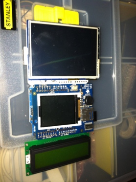
The three screens I have in my collection are:

1.) 2.8″ TFT Touch Shield for Arduino – 2.8″ 

2.) Adafruit 1.8″ 18-bit Color TFT Shield w/microSD and Joystick

3.) 16×2 LCD screen

You can see the three screens side by side below:

Comparison of screen types

Comparison of screen types

Lets start by looking at the 2.8″ TFT touch screen.

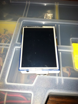
2.8″ TFT touch screen

This device is an Arduino shield and a very nice one at that. It plugs straight into the top of your board ( I have been using an Uno) and there are some libraries available from the Adafruit site to start testig it out.

The screen is large and easy to use which is nice, and the picture quality is good. Being touch screen it also has the benefit that I wouldn’t need to use buttons on my thermostat as manual override/control could be performed directly on the screen.

Touch screen shield

Touch screen shield

The down side to the shield though is that it is very greedy when it comes to pin use.

I tried wiring up my all in one thermistor/resistor unit to the Arduino, plugged in my Ethernet shield with the screen and hit some problems. When the shield initializes it uses some of the pins that the Ethernet shield uses, and vice versa.

At this point I hadn’t tried to hook up any relays which I will also need to switch the mains power on and off to the baseboard heater. The screen may work with some modifications but considering I have other options I will hang on to it for now and use it in another part of the system.

I suspect this shield will be better placed on a wireless thermostat device that uses a Xbee radio for communication, although I will have to do some more experimentation here.

So all in all it is a great shield but isn’t right for the particular style of thermostat I am building at the moment.

1.8″ TFT shield  

The next option was the TFT shield that comes complete with a miniature joystick and SD card reader.

This is a neat little device that requires minimal soldering (just some headers) and then acts as an Arduino shield. It has a nice screen and the added bonus of an SD card slot for loading up images to the device. The Arduino pins can be accessed along the top of the board so unused pins can still be used.

1.8" screen

1.8″ screen

I like this shield a lot, although I have some concerns about whether the joystick-button combo is right for the thermostat. Ideally I would like a few buttons that are always visible. With the previous TFT shield I could literally draw the buttons out and display them at the base of the screen at all times.

With this device, whilst this is possible, to navigate between the options would require using the joystick which may be awkward depending on the angle of the thermostat on the wall. I also feel as if the SD card slot would be wasted on this project as the thermostat has no use for it.

Having done some experimentation with it I decided against using this device for this particular thermostat and will hold onto to it until I can find a project that requires a screen + SD card reader.

16×2 LCD screen

My final option is the LCD screen. This certainly doesn’t have the polish that using one of the top two devices has and lacks the richness in GUI options.

On the plus side it is small allowing space for extra buttons and uses a minimal number of pins. Also not being a shield allows me to hook this up onto a proto-board along with a relay and the thermistor reducing the stacking of components and making my device slimmer. I could get away with just three boards, the Uno, the Ethernet and the Proto.

LCD screen

LCD screen

What I will loose in visual polish I will make up for size. This seems like a fair trade off.

Having played around with the screen I think I can make this work and will use it for the Ethernet thermostat.

This just leaves me with designing a proto-board that contains the screen and other components. For $16 I can get a Makershield from Makeshed and solder my devices to it easily.

So all-in-all this seems like the best path forward.

Conclusion

The LCD device while not the best looking will do the job. My next post on the Ethernet thermostat will look at starting the construction process and review all the components necessary. I’ll also be showing some experimentations I have done with a relay shield and mains power.

The past few weeks have seen some experimenting with the Arduino-to-Raspberry Pi shield so expect a post on that soon, as a heads up it is very cool!

Thermostats – Part 3 – The Ethernet Model prototyping

Introduction

As part of my heating system I have discussed how I am building a set of thermostats that can control the baseboard heaters in my house. The vast majority of these heaters are not located near my PC, electrical box or any of my other computer hardware.

However there is one, that is located in my office close enough to my router that I can connect it up via Ethernet rather than WiFi.

This post will begin looking at prototyping the Ethernet model. A prototype is a handy way of testing the components we have purchased and experimenting with the equipment before we solder it together.

Components required

For the Ethernet model of the thermostat the following components are required:

  1. Arduino Uno
  2. Temeprature sensor
  3. Visual display unit
  4. Ethernet shield
  5. Buttons/manual method of input
  6. Power supply
  7. Ethernet cable
  8. Relays

The picture below shows a group of components I purchased to build the Ethernet model and to prototype with. It includes:

  1. An Arduino Uno
  2. Seeed Studio Ethernet Shield
  3. Temperature sensor purchased from Adafuit – AM2302
  4. All in one TFT screen + button joystick – 1.8″ TFT
Thermostat components

Thermostat components

First steps are prototyping

The prototype we will be exploring below will build a simple thermometer.

For the prototyping I will not  be using the TFT Shield to start with. This is primarily because I am evaluating screen types, which are the best and which ones are better suited for certain locations in the house.

There is a separate post in the works for this, and the outcome of that evaluation will result in the chosen screen type when I blog about turning the Ethernet prototype into the production model.

So to start with we will hook up Arduino, Ethernet shield and temperature sensor and test it works.

For the temperature sensor there is code available via the Adafruit site for testing purposes. This can be downloaded here, along with the instructions for wiring up your equipment.

The picture below shows the temperature sensor wired up.

Temperature sensor

Temperature sensor

Once the sensor was wired up I tried out a few of the test sketches that could be downloaded from the above link. Once I was happy this worked, I then attached the Ethernet shield to the Arduino and attached the temperature sensor to the Ethernet shield.

The picture below shows this setup. Note: At this point I haven’t done any soldering.

Ethernet shield

Ethernet shield

File->Examples->Ethernet->Web server

example.

Modify the settings in the code to assign it an IP# for your local network and upload it to your Arduino. Once done, you can plug in the Ethernet shield to your router and access the IP# you assigned it via a browser on a home computer or tablet.

If you receive the “analog input” message on your screen as a web page, your test has been successful.

For our next test we are going to merge some of the code from the web server example and the temperature example that you downloaded from the Adafruit website.

First, attach your Arduino back to your PC if it isn’t already setup.

Ethernet and Thermostat

Ethernet and Thermostat

Take the following test code and paste it into the Arduino IDE.

Test code.

/*
 Web Server

 A simple web server that shows the value of the analog input pins.
 using an Arduino Wiznet Ethernet shield. 

 Circuit:
 * Ethernet shield attached to pins 10, 11, 12, 13
 * Analog inputs attached to pins A0 through A5 (optional)

 created 18 Dec 2009
 by David A. Mellis
 modified 4 Sep 2010
 by Tom Igoe
 modified 18 Oct 2012
 by Andy Dennis

 DHT test

 Returns temperature and humidity.

 modified 18 Oct 2012
 by Andy Dennis  

 */
#include "DHT.h"
#include <spi.h>
#include <ethernet.h>
#define DHTPIN 2 // what pin we're connected to
#define DHTTYPE DHT22 // DHT 22 (AM2302)
// Enter a MAC address and IP address for your controller below.
// The IP address will be dependent on your local network:
byte mac[] = { 0xDE, 0xAD, 0xBE, 0xEF, 0xFE, 0xED };
IPAddress ip(192,168,1, 177);
DHT dht(DHTPIN, DHTTYPE);
// Initialize the Ethernet server library
// with the IP address and port you want to use 
// (port 80 is default for HTTP):
EthernetServer server(80);
void setup()
{
  // start the Ethernet connection and the server:
  Ethernet.begin(mac, ip);
  server.begin(); 
  dht.begin();
}
void loop()
{
  float h = dht.readHumidity();
  float t = dht.readTemperature();

  // listen for incoming clients
  EthernetClient client = server.available();
  if (client) {
   // an http request ends with a blank line
   boolean currentLineIsBlank = true;
   while (client.connected()) {
     if (client.available()) {
       char c = client.read();
      // if you've gotten to the end of the line (received a newline
      // character) and the line is blank, the http request has ended,
      // so you can send a reply
      if (c == '\n' && currentLineIsBlank) {
        // send a standard http response header
        client.println("HTTP/1.1 200 OK");
        client.println("Content-Type: text/html");
        client.println();

        // check if returns are valid, if they are NaN (not a number) then something went wrong!
        if (isnan(t) || isnan(h)) {
        client.println("Failed to read from DHT");
     } else {
        client.print("Humidity: "); 
        client.print(h);
        client.print(" %\t");
        client.print("Temperature: "); 
        client.print(t);
        client.println(" *C");
     }

     break;
   }
   if (c == '\n') {
     // you're starting a new line
     currentLineIsBlank = true;
   } 
   else if (c != '\r') {
     // you've gotten a character on the current line
     currentLineIsBlank = false;
   }
  }
 }
 // give the web browser time to receive the data
 delay(1);
 // close the connection:
 client.stop();
 }
}

The above code is simply a combination on the Web server sketch and DHTester sketch combined.

You can modify the IP# on this to assign it one on your home network and change the output message if you like.

Now upload this to your Arduino and hook it back up to your router.

With your PC/Tablet, now hit the IP# you assigned it via your web browser. You should see something like the following (provided you didn’t modify the message)

Humidity: 52.3% Temperature: 26 C

This confirms that the temperature sensor is working, and the data can be output via HTTP over Ethernet.

Next Steps

Obviously this is a very simple example, and doesn’t do what we need it to yet. However it demonstrates some of the technologies we plan to use, and also confirms that our components are working. We also have a working thermometer as a by-product of our tests.

Our next steps will be as follows:

1.) Choose the correct VDU (visual display unit)

2.) Test the VDU alongside the prototype code

3.) Write the code to output the temperature over HTTP and to send the data back to the Raspberry Pi

4.) Write the code to manipulate the baseboard heaters

5.) Solder the components together

6.) Place them in a case

7.) Wire the new thermostat unit into the baseboard heater, and attach it to the wall.

I’ll be blogging on the above to provide an easy guide to completing the production model, and also adding the code to BitBucket.

Summary

The above example has shown that a quick prototype can be used to test our components before writing a lot of code and soldering equipment together.

The next post in this series will be dedicated to testing the VDU and assigning one to the prototype that is easy to use and displays the data we need it to.
HTSQL – an HTTP based query language

An introduction to HTSQL

I’ll quickly give you an over-view of what HTSQL is, before I go into how I plan to use it for my thermostat/heating project.

HTSQL is a query language, developed by Clark Evans and Kirill Simonov of Prometheus Research, for relational databases that can be used over http. The language contains many of the features available in SQL but with the benefit that the user can plug queries directly into their browser, rather than having to embed code into server-side scripts, or connect to a database directly via a command line.

A variety of relational databases are supported by HTSQL including (but not limited to): MySQL, PostgreSQL, MsSQL and Oracle.

Once you have installed HTSQL you can point your instance at an existing database and begin to query the data contained within it. For example, if I wished to return a JSON object containing a list of temperatures from a temperature table, the query could look something like this:

http://myheatingserver:8080/temperature/:json

I could post the above URL into my web browser and it will query and return the data for me.  This of course opens up a lot of possibilities for a heating system dashboard, web-based monitoring and secure remote access of data.

There is a comprehensive list of examples of the HTSQL language here. The language is also complimented by a JavaScript based toolkit (HTRAF) that allows users to embed queries directly into widgets in their HTML page, and generate HTML elements dynamically.

Applications of HTSQL in my heating system

As I alluded to above, HTSQL provides some great opportunities for building dash boards and similar. I plan to use the technology in a number of ways, some of these are briefly outlined below:

1.) Install HTSQL on the Raspberry PI. Once installed on the RPI, I can point it at my local database server (more on this later). If I wish to switch the server out at any point in the future, I can update the settings on the RPI with little problem.

2.) Use my Arduino thermostats to post data to my DB server via HTSQL. The Arduino thermostats will be able to construct HTTP requests that will post temperature data to the RPI running the HTSQL instance. HTSQL will then take care of the rest.

3.) Modify heat setting in various rooms via the RPI. The algorithm that will guide changing the temperature in various rooms in my house will be located on the RPI. Via the HTSQL server it will be able to access past temperature history and use this for optimization.

4.) Build a dashboard to show temperature history and a host of other data. On a separate web-server I’ll be setting up (probably an Apache web-server on Ubuntu) I can build a graphical dashboard using HTRAF widgets to present the data I have collected in graphs, tables and other interesting HTML elements.

No-doubt other uses will arise as I start to build out my system and I’ll post these uses as I go. As I hope you can see from the above, the language provides some very interesting tools!

Conclusion

HTSQL provides a great method for interacting with and querying my heating system. My next step is going to be installing HTSQL on my RPI running Debian Squeeze. I’ll provide a guide to this as I go, as well as a guide to installing HTSQL on my MacBook for testing purposes.

Quick update

I have exams coming up in the next two weeks, so the blog will be a little on the quiet side. However once the exams are complete expect a flurry of posts on the Thermostats progress.

In other news, Cnet reports that the Raspberry PI has started shipping. You can read about it here. We are also expecting delivery of the MakerBot in the next two weeks.

Thermostats – Part 2 – Arduino setup

In my previous post I blogged how I had purchased an Arduino Uno, shown below, I’ll now give you a quick intro on the setup.

img_0216

First of all you will need a USB cable, this isn’t included with the Arduino Uno, unless you purchase a kit which includes the Uno and other components. The USB cable needs to be  a USB A-Male to a USB B-Male.  I’ve attached a screen shot of this below:

USB cable

USB cable

You can see the USB port (and power) on the Arduino below:

USB port

USB port

I plugged this in before downloading the development environment and it lit up straight away (the board runs on USB power, as well as a standard power cable which also isn’t included).

Arduino plugged in

Arduino plugged in

Next you will need to download the Arduino IDE (Integrated Development Environment). This can be found here. There is a version for Mac OS X, Windows, Linux and for those of you who wish to compile the IDE yourself, the source code.

Once you have followed the process to set up the Arduino IDE then you should be good to go. You can also find a quick guide to the IDE toolbar here.

I experimented with a few of the test applications that can be found in the IDE  to get the hang of things. A list of this examples can be found on the Arduino site here. Also the language reference guide can be found here. And yes the Arduino language even includes a goto statement which I am sure has caused no end of debates online!

So that’s it, an incredibly easy piece of hardware to get setup.

My next step is going to be exploring the Arduino programming language.

Thermostats – Part 1

Overview

Having decided to replace the existing thermostats with a set of home-brew ones that can communicate wirelessly, I now need to find out  which hardware is required and get a basic drawing together of how the components will interconnect.

I found the following two websites incredibly useful as they gave an overview of projects other bloggers had completed:

http://mcmicken.ca/tag/arduino-thermostat/

http://www.desert-home.com/p/super-thermostat.html

So it looks like the thermostat will contain the following basic hardware components:

  1.  Main board (micro-controller)
  2. Temperature sensor
  3. Wireless shield
  4. Power source
  5. LCD display
  6. Over-ride buttons
  7. Wall mount
  8. Casing

I am going to start with the micro-controller. This acts as the base where I can then start to work out which components will fit onto it easily and map out how they will interact.

Arduino – Microcontroller

The other day I received a $10 coupon for Radio Shack, so I stopped by and picked up a couple of Arduino boards there. Radio Shack is more expensive than ordering online, so in future I’ll be picking up components on the web.

The boards I picked up were the Arduino Uno:

Arduino Uno

Arduino Uno

and the Arduino Proto:

Arduino Proto

Arduino Proto

The Arduino Uno is an open-source micro-controller and part of the Arduino platform, an easy to programme open source hardware and software environment.

The Uno can have a number of sensors and other components hooked up to it, and then programmed using the Arduino programming language, which is based upon Wiring (an open-source programming framework)

This piece of hardware will act as a good micro-controller for the Thermostat. Newark Electronics (the folks from whom I ordered my Raspberry PI) are also selling the Uno for $25.50 a piece. This makes replacing the existing thermostats a fairly cheap process.

As you can see in the photos above, there is also the Proto. The Proto can be used for designing custom circuits. Having this will allow me to try out some custom circuit designs before I solder components to the Uno.

I’ll now need to hook up the Uno to my Mac and download the development environment so I can start playing around with it.

The book I purchased Programming your home, has some great starter projects that will give me some practice with the programming language and the development environment in general.

The next post will detail hooking up the Arduino and getting a hang of the interface and IDE.