pfSense and SNMP – Introduction

Introduction

It’s useful to be able to monitor devices on our network for a variety of reasons including security and performance issues. In this post we are going to provide a brief introduction on ow to do this. This post will form the foundation for future ones which dive into the subject further.

Our pfSense firewall supports the protocol known as SNMP (Simple Network Management Protocol) which allows us to do exactly that over a TCP/IP network. Many tools exist out there, but we will be experimenting with this one in particular since it is easy to install for learning purposes.

For those interested it operates at Layer 7 of the OSI-7 Layer model (the Application layer). A range of devices from servers to printers support the protocol and this list of devices also includes pfSense.

There are many use cases for SNMP.  If we build out our own server which acts as the management console for our home automation devices, it would be good to gather data on it and alert us if we need to administer it in some fashion. Or perhaps we wish to perform the same task on a firewall!

Each of these devices represent agents on our network.  Once we have the SNMP client software installed on the agent it will expose a set of variables to the management console which then allows us through these variables to update configuration and similar.

In this instance pfSense will act as the agent and will be administered by a management system running on a Linux based device.

For the purposes of this series of articles we will be using a simple Raspberry Pi 3 running Linux as an example of how to build out a management device and collection point for TRAPs.

Once you have the basics in place and are comfortable with how SNMP works you can roll it out to intelligent thermostats you may have built with the Raspberry Pi or similar devices.

To recap we therefore four components in this project:

  1. A Raspberry Pi – the manager
  2. The agent – the software running on pfSense
  3. pfSense firewall hardware -the managed device
  4. NMS (Network Management System) – the software component on the Raspberry Pi

Let’s take a quick look at the SNMP protocol before we start configuring our devices to familiarize ourselves with the features.

SNMP version 1.

Version 1 of the SNMP protocol introduced three important operations to interact with managed devices on an IP networks. These are GET, SET and TRAP

GET – This allows the management station to retrieve an object from an entity

SET – Allows the management station to SET objects on a managed entity

TRAP – Allows the entity to notify the management console of significant events.

SNMP version 1 also introduced the MIB. The Management Information Base contains configuration data and operational information. You’ll see a bit more about this later when we use a tool to walk through it, however here is an example of the data:

iso.3.6.1.2.1.1.1.0 = STRING: “pfSense pfSense.localdomain 2.3.2-RELEASE pfSense FreeBSD 10.3-RELEASE-p9 amd64”

Another important feature is the community name. Devices in the same community could authenticate with each other using this method.

There are a number of flaws in SNMP version 1. Security is very weak with the community name acting as a user group and password rolled into one.

In addition to this freshness checks e.g. nonce or timestamps are absent so replay attacks are possible and finally none of the data is encrypted.

SNMP version 2c.

SNMP version 2c  is almost identical to version 1, but has subsequently been superseded by SNMP version 3 which beefed up security relative to version 1. Version 2c added in the support for 64 Bit counters.

SNMP version 3.

In version 3 of the protocol we now have keys which are used to encrypt traffic from one device to another.  The device whose keys are used to provide auth/confidentially is known as the authoritative entity.

For GET/SET the receiver is the authoritative entity.

For TRAP the sender is the authoritative entity.

Another feature of SNMP version 3 is the SNMPEngineID which acts as a unique identifier for an entity on the network.

Those that’s a quick overview of the protocol. You can read more about here if you want to learn more.


Setting up the Raspberry Pi.

Our Raspberry Pi will eventually end up being our management console. However first we will install some basic tools on the device so we can monitor it from itself for learning purposes as well as review the MIB on the pfSense appliance.

Log in to your Raspberry Pi (or similar Debian based Linux device) and run the following commands:

sudo apt-get update
sudo apt-get install snmpd
sudo apt-get install snmp

Once the installation has finished we can edit the configuration file that contains the settings for SNMP on your device.

Using vim or a similar tool edit the snmpd.conf file e.g.

sudo vim /etc/snmp/snmpd.conf

Find and comment out the line with agentAddress and change it to the following:

agentAddress  udp:161

Then change the rocommunity to mysnmptext

rocommunity mysnmptest

Save the file and exit.

We now have our agent running on port 161 which is standard and using UDP (User Datagram Protocol).

Let’s now restart the services.

sudo service snmpd restart

We can check the process if running by running the following command:

ps -A | grep snmpd

You should see an output similar to the following

 2232 ?        00:00:00 snmpd

We can walk the MIB on the Raspberry Pi using a tool called snmpwalk.

To do this we need to run it using the community name (mysnmptest) then version (1) and the target machine (localhost).

Run the following command from you terminal:

snmpwalk -Of -c mysnmptest -v 1 localhost

You should now see some output similar to the following which is the OID and its value :

iso.3.6.1.2.1.1.1.0 = STRING: “Linux raspberrypi 3.18.7-v7+ #755 SMP PREEMPT Thu Feb 12 17:20:48 GMT 2015 armv7l”

The labels aren’t much help in defining what each of these output items mean in many cases. Therefore we are going to install the snmp-mibs-downloader library to resolve the OID to their text description.

From the command line run:

sudo apt-get install snmp-mibs-downloader

After this has completed, edit the conf file:

sudo vim /etc/snmp/snmp.conf 

We don’t need the mibs value, so go ahead and comment this out

#mibs

Save and exit the file.

Now let’s try rerunning the command again:

snmpwalk -Of -c mysnmptest -v 1 localhost

We should see the OID resolve to a string prefix now:

.iso.org.dod.internet.mgmt.mib-2.system.sysDescr.0 = STRING: Linux raspberrypi 3.18.7-v7+ #755 SMP PREEMPT Thu Feb 12 17:20:48 GMT 2015 armv7l

Here we can see the sysDescr i.e. System Description is the Raspberry Pi as expected.

Now we have tested this on the Raspberry Pi, let’s enable the option on pfSense.

Configuring pfSense

Enabling SNMP on pfSense is fairly straight forward.

You can access the SNMP settings through Services > SNMP

The following screen will be displayed

SNMP

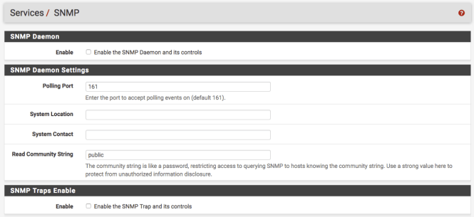
First select the Enable option. This turns the daemon on.

Next in the System Location assign value e.g. “firewall”. Following this you can also add a System Contact e.g. yourself.

We are now going to change the Read Community String to mysnmptest which is what we assigned to community value on the Raspberry Pi.

Scroll down to the bottom option and set the Bind Interface to LAN. We only want this enabled on our local network, and certainly not the WAN.

Don’t worry about the other settings. We will re-visit the TRAP options in a later post.

Save the updates.

Testing our setup

We can use the tools we installed on the Raspberry Pi to query the pfSense box. return back to the command line and run the following:

snmpwalk -Of -c mysnmptest -v 1 192.168.1.1

This is the same as we did with the Raspberry Pi, however we have changed localhost to the be the IP of the firewall.

You should see a response similar to:

.iso.org.dod.internet.mgmt.mib-2.system.sysDescr.0 = STRING: pfSense pfSense.localdomain 2.3.2-RELEASE pfSense FreeBSD 10.3-RELEASE-p9 amd64

In this case the sysDescr is the pfSense firewall description.

So there we have it. SNMP clients setup in two locations and a method to review each devices MIB.

Conclusion

This post briefly introduced us to SNMP and installing it on the pfSense firewall and a secondary Raspberry Pi. We explored version 1 of the protocol. Future posts will cover how we can use this data for monitoring and more information on the OIDs.

In addition to this we will set up SNMP TRAPs and also look and SNMP version 3.

VPNs, firewalls and VLANs for Home Automation – Part 5: pfSense security features: TLS

Introduction

In this post we will be briefly looking at one of the security features available in pfSense – TLS. TLS stands for Transport Layer Security and is one of the building blocks of eCommerce. This will also introduce us to some other concepts such as X.509 certificates which will be useful when we setup a VPN.

TLS protocol

When you log into the pfSense web console you will see we use https in the URL bar. This is because we are connecting on port 443. The service used here is know as Transport Layer Security (TLS).

You will have seen this on eCommerce sites such as Amazon when you purchase goods and is denoted in the browser bar with a little padlock and the https protocol.

Within pfSense the option to set the web console to run over HTTPS (and thus use TLS) can be found on System > Advanced.

Here you will see a radio button selected labeling HTTPS. In addition to this a drop-down can be seen with SSL Certificate. Make a note of the name here as we will cover this later in the post.

TLS also known historically as SSL handles encryption and authentication. In pfSense it is used to provide a secure channel on which to connect to the web console in order to administer the firewall.

Currently when we visit the firewall via https we see an error:

TLS

This is related to the certificates that are used by TLS as part of the authentication process. We’ll look a little more into this error later in the article and how certificates are used as part of the security process.

The overall security services provided by TLS encompass:

  • Origin authentication – client to server at application and transport layer
  • Data integrity – to prevent being compromised in transport
  • Data confidentiality – to prevent eavesdropping

TLS is implemented using a key exchange mechanism, certificate verification and digital signatures. Typically the client authenticates the server and not the other way round – although mutual authentication is possible and supported by the protocol. As you can imagine this would be impractical/unnecessary on an eCommerce website with hundreds of thousands of users and where we would expect them to have their own signed key chain.

However there are arguably places where mutual authentication would be beneficial – such as online banking.

So how does TLS work? Let’s take a look at some of the gory details.

How TLS works

When a client connects to a server, it kicks of the TLS handshake. This process includes negotiating cipher suites, encrypting shared session keys and generating message authentication codes (MAC).

MAC in this instance defines a Message Authentication Code – a hashed version of  a message(s). It shouldn’t be confused with the MAC address on your NIC. So same acronym – different definition.

TLS also uses a key exchange service. This provides for key agreement which is typically achieved by the client sending a secret that has been asymmetrically encrypted to the server.

One of the current methods in TLS 1.2 of doing this is via RSA however this is being phased out in version 1.3. The Diffie-Hellman key exchange is also available in various forms. You can see a list of these formats here.

Let’s take a quick look at RSA as this method is used in a number of other tools we will be using such as SSH.

RSA

The RSA algorithm is made up of four steps, these being the key generation, key distribution/exchange and finally encryption and decryption. RSA is a type of “asymmetric”encryption methodology also known as public key encryption.

The key generation steps are designed to produce two keys; a public key and a private key. The public key can be distributed to multiple machines/users. The private key is kept secret. The methodology for this revolves around using large prime numbers and modular exponentiation.

With the key distribution step we can use RSA to allow us to transfer a symmetric encryption key via an asymmetric key exchange protocol. The public key can be distributed through non-secure channels and then used to encrypt said private session key. Only the owner of the private RSA key can subsequently decode this encrypted message containing the symmetric session key.

Symmetric encryption is generally faster than asymmetric encryption but relies on both parties having the same key. This isn’t practical in most cases or at least without having some form of key distribution mechanism. Examples of these mechanisms include Kerberos and other trusted third parties built around the Needham-Schroeder symmetric key protocol. Of course we can also use public key cryptography as a means of distributing a dynamically generated session key for symmetric encryption.

The fourth step has in essence been described above when discussing key exchanges. To encrypt a message the plaintext is encrypted using the public key and then sent to the other party.  They then use their private key to decrypt the message. The inverse is true. A message can be encrypted with the private key, and decoded with the public.

Many protocols use the public/private key only for setting up a secure channel. In fact after this has been completed we can expect the messages to be encrypted using the shared symmetric keys using the method previously described.

With a quick summary of RSA under our belt let’s take a look at the TLS handshake in more detail.

TLS Handshake

The handshake as we have discussed involves negotiating cipher suites, exchanging keys over RSA and generating MACs.

How this all fits together is demonstrated as follows with two roundtrips:

Client Server
Sends SYN
Sends SYN ACK
Sends ACK
Roundtrip 1. Sends ClientHello including TLS version, random numbers (32-bit nonce) and list of supported cipher suites
Roundtrip 1. Sends ServerHello with random numbers, Certificate and ServerHelloDone
Roundtrip 2. Confirms certificate is OK. Sends ClientKeyExchange, pre-master secret, ChangeCipherSpec,  and Finished message
 Roundtrip 2. ChangeCipherSpec, verify MAC and sends encrypted Finished message.
Decrypts Finish message with symmetric encryption key and checks MAC. Sends application data encrypted.
 Sends application data back and forth
 Sends application data back and forth until connection is closed.

One useful feature of the TLS handshake process is that part of it can be “re-used” across a session. This means if we navigate between multiple webpages, we can leverage the fact we have already completed the 2 round trips. Thus in this latter re-use case only a single roundtrip is used.

TLS components

Digging a little deeper into TLS we can see some of the components that make up the protocol and handshake we saw above.

SSL handshake SSL change cipher spec SSL alert Application data
Record protocol
TCP
IP

The first layer of the protocol contains the components needed for TLS handshake, alerting when the connection is closed and negotiating the cipher suite.

The next layer down is the Record protocol. This takes the data from the previous layer and fragments and encrypts it and also assigns an HMAC (Hashed Message Authentication Code).

Following this we see the TCP and IP layers.

If you would like to read more about how TLS works check out the High Performance Browser Networking guide by O’Reilly. This article includes more information on the handshake and other features of the protocol.

TLS summary

In the above section we have seen how TLS creates a secure channel between your machine and the pfSense box on port 443 to serve up the web console. We also mentioned that certificates are used, so what exactly is their purpose?

Certificates

Certificates are used to identify a party as trustworthy. This is important if you wish to transfer financial data between them and yourselves. They follow the X.509 standard where by a public key certificate chain (called public key infrastructure – PKI) is created. Each certificate is signed by a trusted party and ultimately by a trusted root authority. For example Google, Microsoft or a government department.

As you might imagine from the name, public key certificates are built around the same principles as public key cryptography.

When running the TLS protocol we check the certificate chain of the server to ensure it is trustworthy and the certificate hasn’t expire. If one of these two instances aren’t the case, we see an error same/similar to this:

Chrome cert error

In pfSense by default you will have a self signed certificate called “webConfigurator default”. You will remember this from when we looked at the Advanced screen. This is the certificate assigned to the pfSense box and used as part of the TLS authentication process.

To access the list of certificates on your system select System > Cert. Manager from the main menu.

This will bring you to the CAs tab. From here select Certificates.

On this screen you should see the certificate details and note that the Issuer (the CA) is self-signed. This is why we are seeing the error as the certificate is not signed by a trusted root.

As this is our local network we do not need to worry about purchasing a signed certificate. If you are interested in importing the self signed certificate however and trusting it in your browser – you can follow the steps here and also here for Mac users.

When we come to setup a VPN we will be creating a CA and also client and server certificates. More on this however in further posts.

Summary

In this post we briefly looked at TLS which explained the error we see when we login to pfSense web console. In addition it very briefly introduced us to RSA and X.509 certificates.

These topics will be covered in more detail in later posts. Next we will look at some further features in pfSense.