Introduction
In this post we will be setting up the pfSense firewall and disabling the features on our cable companies modem/router combo.
Before we start with the pfSense install however, we will quickly cover a little bit of theory on the OSI-7 Layer model and TCP/IP model. Following this we will examine what firewalls are then apply this knowledge to pfSense.
This background information will help when coming to understand how the firewall, VPN and TLS work together in later posts.
Let’s start with a (very) brief overview of the OSI and TCP/IP protocol stack.
OSI-7 Layer and TCP/IP protocol stacks
Fundamental to how networks work is the idea of the OSI-7 Layer and TCP/IP protocol stacks.
Both of these stacks essentially describe the same thing: the creation of packets of data that are sent across a network between machines to allow for communication.
The OSI-7-Layer representation is as follows:
| 7. Application – Here we find application level protocols such as HTTP |
| 6. Presentation – Concerned with both how data is represented/encoded and transferring data in a language or syntax that the receiving machine can understand. The encoding technique is covered by Abstract Syntax Notation (ASN). |
5. Session – This layer handle the sessions between machines for tasks such as file transfer. Within this layer there are two main services:
|
4. Transport – At the Transport layer data is passed into it from the Session layer and is divided into smaller units and then passed to the next layer (Network layer). At this layer the type of service that will be provided is decided, for example:
|
3. Network – The Network layer provides a uniform addressing scheme for network addresses and also provides two services, these being:
|
| 2. Datalink – Used for providing error-free transmission service for data. Data is handled as frames. |
| 1. Physical – This is the lowest level of the stack and handles how data is transferred from binary format into voltage over the line. |
Each layer of the stack offers services to those above (Layer N + 1), these are accessed at the service access point (SAP).
Data is passed down the stack via SDU’s (Service Data Units) which encapsulate a PDU. A PDU (protocol data unit) is a virtual unit of communication between two machines. These contain information such as headers and sequence numbers. Thus the PDU is passed to the corresponding layer of the stack on the counterpart machine.
Note: A PDU at each layer of the stack may be known by an acronym such as APDU (application Data Unit).
The Internet (TCP/IP) model was an alternative model proposed to that of the OSI-7 layer. It’s geared towards TCP/IP protocols (as the name suggests) which underpin the Internet.
TCP standard for: Transmission Control Protocol.
This model is demonstrated below, as you can see it is simpler and some of the layers overlap either directly or in part with the OSI-7 layer model:
| Application – Corresponds to the OSI Application, Presentation and Session layer |
| TCP – This layer corresponds to the Transport layer. Here we find the TCP segment. |
| IP (Internet) – The Internet layer matches sections of the Network layer. Here we find IP packets. |
| Network – This layer overlaps with the Network layer and encompasses the Data link layer |
| Hardware – This matches the Physical layer in the OSI model |
TCP/IP relies on two important packet types, those being:
- TCP – a connection orientated protocol. Its protocol units are known as segments
- UDP – a connectionless orientated protocol. Its protocol units are called datagrams
As with the OSI-7 layer model PDU’s (known as segments) are passed down the protocol layers in SDU’s at SAP’s. Finally they are converted into voltage, sent out onto the wire, and the reverse process happens at the other end.
When dealing with firewalls there are some important things we need to know about some of the above layers of the TCP/IP model and the data sent back and forth.
Namely:
- The IP layer is concerned with the IP address information contained in the IP datagram. The IP address being a numeric identifier of a machine.
- The TCP layer is concerned with the port information contained in the datagram/segment. The port number is a numeric value detailing where a software service is running.
When we examine data coming in and out of the firewall these two pieces of information will become important in deciding what rules we wish to configure. In addition to this the type of packet will also come into play (for example UDP versus TCP).
You may find that referring back to these helps when we discuss aspects of how a firewall works next.
Firewalls an overview
Firewalls are responsible for filtering traffic in and out of a network. Generally speaking there are four types of firewall, these being:
- Packet filtering firewalls
- Circuit-level proxies
- Stateful packet filters
- Application-level proxies
In addition to this we have two special case firewalls:
- Web Application Firewalls (WAF)
- Personal Firewalls
Stateless packet filtering firewalls
A packet filtering firewall will look at incoming/outgoing packets that a router wishes to route to a destination machine, and decide whether to block the packet or not. This blocking could take the form of disregarding the packet, or responding to the sender with a notification of failure.
The criteria it will typically use to block a packet include source/destination IP and source/destination port number. This criteria is controlled by a rule set. You’ll see in pfSense later (which is in fact a stateful firewall) how we can configure a rule set.
Rules in this type of firewall need to be configured for both client to server and server to client, which can be fairly onerous to manage.
As we saw above the port number and IP address are contained within our TCP/IP packet. Thus a packet may contain a valid IP address at the IP layer, but the port specified at the TCP layer is blocked.
Circuit-level proxies
A circuit-level proxies firewall works in a slightly different fashion to the packet filtering firewall.
Rather than filter and route packets to machines on the network, it in fact takes the incoming packet and re-creates it if valid against the firewall ruleset. Thus the firewall acts as a proxy, taking incoming and outgoing packets, examining the contents and recreating and sending if valid.
This adds an important security aspect to the firewall. The packets being sent to and forth from the firewall will thus only contain information about the firewall. This is rather than that of the system that sent the original packet e.g. your local Linux machine. Thus the firewall obfuscates information that may be used to construct attack vectors by a malicious party.
Stateful packet filters
The next type of firewall is the stateful type and pfSense falls into this category. Stateful firewalls are one of the most common types found today and provide a good compromise on performance, ease of use and security.
A stateful firewall allows you to configure a single rule such that reply packets from a server to client are handled by the same rule as the client to server. Ancillary packets related to the connection can also be recognized by the rule without the need to configure further rules.
Thus a single firewall rule for connections can handle reply packets, and the nuances tailored at the client-to-server rule level. When a connection ends between the client-and-server further communication via the path is blocked as the state of the connection is closed.
This will all become clearer when we configure pfSense.
Application-level proxies
As the name may suggest the Application level proxy firewall, is concerned with filtering traffic at the Application layer. In addition to this, it checks the port number of the destination packet is associated with the application.
As the with the circle level proxy, the packet is not routed, but re-created. However there is one very big difference that should be explained.
The application level proxy firewall contains a complete representation of the OSI-7 layer protocol in both client and server form (rather than just server form) for each supported protocol.
Thus to support voice, email, HTTP, video etc. a model of each needs to be present within the firewall software. This allows far more granular security and allows the application to block certain aspects of a supported protocol.
For example if we wish to only support HTTP POST requests at the firewall level, we can block DELETE, GET, PUT etc.
For a home network this may be overkill, however it could be argued for a subnetwork consisting only of IoT devices this may be incredibly useful, if requiring a large overhead to maintain.
Next we will briefly touch upon our two special case firewalls.
Web Application Firewalls (WAF)
Web Application Firewalls are a software based service that allows us to filter out traffic that may be considered harmful., This could be DoS style attacks that attempts to SYN flood a network, SQL injection attacks, XSS attacks or similar attempts to compromise a website/network.
While not directly applicable to what we are concerned with in our home IoT network, they are never-the-less interesting to understand.
You can read more about them at the OWASP website.
Personal Firewalls
Last but not least is the personal firewall. You may be familiar with this type of software as it can be found in operating systems such as Windows. It’s designed to protect a single machine, especially in the past those that connected directly to the Internet via dial-up.
Now we have quickly run through the firewall types available and a bit about the networking protocols around them, let’s take a look at pfSense.
pfSense – An Introduction
The pfSense firewall is an open-source application wth many of the features found in (expensive) commercial firewall products. It is built on-top of the FreeBSD operating system.
The current version 2.4 includes:
- Firewall with stateful packet inspection
- Easy to use Web Based Graphical Interface
- Installation Setup Wizard
- Configurable Dashboard with many available widgets
- IPv4 and IPv6 support
- Wireless Access Point (must install a wireless interface which supports hostap mode), including VAP/MBSS support on certain chips.
- Wireless Client Support (802.11 and 3G/4G with supported devices)
- Ability to setup and filter/isolate multiple interfaces (LAN, DMZ, etc.)
- Traffic Shaping
- State Table controls (per-rule / per-host limits, timers, etc.)
- NAT (Port Forwards, 1:1 NAT, Outbound NAT, NPt)
- Redundancy/High Availability – CARP+pfsync+XMLRPC Config sync allows for hardware failover. Two or more firewalls can be configured as a failover cluster.
- Multi-WAN Support
- Server Inbound Load Balancing
- Network diagnostic utilities such as ping, traceroute, port tests via the GUI (more with packages, such as nmap)
- VPN – IPsec (including Phase 2 NAT), OpenVPN, L2TP
- PPPoE Server
- RRD Graphs
- Real-time interface traffic graphs
- Dynamic DNS
- Captive Portal
- DHCP Server and Relay (IPv4 and IPv6)
- Command line shell access (Via console and SSH)
- Wake on LAN
- Built in packet capture / sniffer
- Ability to backup and restore the firewall configuration via the web GUI
- Edit files via the web GUI
- Virtual interfaces for VLAN, LAGG/LACP, GIF, GRE, PPPoE/PPTP/L2TP/PPP WANs, QinQ, and Bridges
- Caching DNS Forwarder/Resolver
- Can be run in many virtualization environments
- Proxy Server (using packages)
Many of these terms may be new to you, but those that are important will be covered over the series of posts.
For those interested a pre-installed version of the software can be found bundled with Netgate’s custom firewall hardware.
If using an existing hardware option then pfSense can be downloaded directly from the pfSense website here. They also provide a handy guide to building/purchasing hardware specifically to support pfSense.
Once your hardware has been selected, follow the installation guide located at the pfSense wiki.
As per the wiki once installation is complete, the following default configuration options are in place:
- WAN is configured as an IPv4 DHCP client
- WAN is configured as an IPv6 DHCP client and will request a prefix delegation
- LAN is configured with a static IPv4 address of 192.168.1.1/24
- LAN is configured to use a delegated IPv6 address/prefix obtained by WAN (Track IPv6) if one is available
- All incoming connections to WAN are blocked
- All outgoing connections from LAN are allowed
- NAT is performed on IPv4 traffic leaving WAN from the LAN subnet
- The firewall will act as an IPv4 DHCP Server
- The firewall will act as an IPv6 DHCPv6 Server if a prefix delegation was obtained on WAN, and also enables SLAAC
- The DNS Resolver is enabled so the firewall can accept and respond to DNS queries
- SSH is disabled.
- WebGUI is running on port 443 using HTTPS
- Default credentials are set to a username of admin with password pfsense
Our next step is going to be to connect pfSense up to our ISP via the modem/router combination. When we do this, we will disable the routing options on the device so that pfSense can handle our LAN.
What this will mean is that:
- Traffic will pass through the ISP modem un-filtered (some traffic filtering may happen at the ISP level however prior to reaching your device)
- pfSense will act as the firewall for filtering traffic
- The DHCP server in the ISP cable modem/router combo will no longer be responsible for handing out IP addresses to machines on your network.
For those of you who own your own device and do not use the ISP’s you should set your router and/or modem up to pass traffic directly through to pfSense.
This is typically known as Bridging and router/modem combos often have a Bridge Mode. This mode transparently links two networks: the ISP and your home network.
Googling your modem/router combo should provide you with instructions on how to switch it to Bridge Mode.
Disabling routing in the modem/router combo also avoids a problem known as Double NAT (Network Address Translation).
Double NAT
The NAT service effectively translates traffic from your external IP (provided by the ISP) to the internal IP address assigned to the router.
In the case of double NAT, the external IP assigned by the ISP has to be translated into the modem/router combo’s internal IP that is assigned to your secondary router. Then once again translated from this internal IP address (assigned to your secondary router) to the internal IP address of said router.
This doubling up is a bid of a headache and redundant to boot.
Connecting to the firewall to the modem
The following stage of our setup will see Internet connections on your home network interrupted until setup is complete. For these steps you will need an ethernet port on your laptop/desktop. Newer Mac’s such as those with USB C only ports do not include this by default, so a Ethernet dongle is a useful addition to your toolkit.
What we are going to do is connect the modem in Bridge Mode to the pfSense firewall. This will direct all web-traffic through to the firewall.
Following this, we will configure the firewall to act as a DHCP server.
The DHCP server (Dynamic Host Configuration Protocol) is responsible for assigning IP addresses within a set range to machines that connect to the firewall LAN (Local Area Network). We will see in later posts how Wireless Access Points (WAPs) can leverage this feature, as well as VLANs.
To get our initial setup, up and running complete the following steps:
- Connect your modem to the pfSense hardware device. Both devices should be powered off.
- Connect an ethernet cable from the WAN port on the pfSense device to the LAN port of the modem.
- Next attach your laptop or desktop device to the LAN port of the pfSense device via ethernet.
- Power all of the devices on and give them a few moments to boot up.
- With your attached machine, navigate to the following IP address in a browser: https://192.168.1.1 – This is the default IP address that pfSense uses.
Depending on your browser you should expect to see an error message similar to the following (Chrome browser):
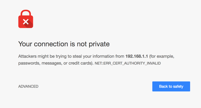
This is due to the fact we are trying to access the Web console over HTTPS (SSL/TLS) connection and the certificate authority is considered invalid.
We’ll cover more on TLS in later posts and how this protocol works.
Click Advanced (or similar depending on browser) and then Proceed to 192.168.1.1 (unsafe).
You will now be presented with the pfSense web console login.
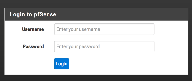
By the default the password and username are:
- username of admin
- password of pfsense
Once logged in the pfSense dashboard will be presented. Along the top of the screen is the menu that provides short cuts to the major sections of the firewall:

On the right hand side of the screen you will see in the top right a list of interfaces.

Next to this is the ISP IP address of the WAN and LAN with the pfSense devices IP.
Our first task once logged in is going to be update the password of the admin account.
Change admin password
From the System menu:

Select User Manager.
On the screen presented you will see the admin user account. From this screen select the pencil icon next to the admin user.
You will be presented with a screen allowing you to edit the user details. Change the password for the admin on this screen, then use the blue Save button at the bottom of the page to update the changes.
Now logout of pfSense using the icon in the top right:

From the login screen, log back in.
Next let’s take a look at the firewall rules.
Basic firewall rules
By default we want to allow Internet traffic in and out of the firewall. You should find by default the firewall is configured to allow all IPv4 TCP and UDP traffic to and from the LAN.
You can test this by trying to access Google or a similar website.
We can check that the rule is indeed enabled, by going to Firewall > Rules from the menu at the top of the pfSense screen.
Select the LAN tab from the list presented. On the screen that loads you should see the following rule:

If for some reason the rule is missing, we can add the rule as follows.
Adding a rule – quick guide
To add a new rule click one of the Green Add buttons (there are two to choose from, and these simply add the rule above or below an existing one, so either will suffice):

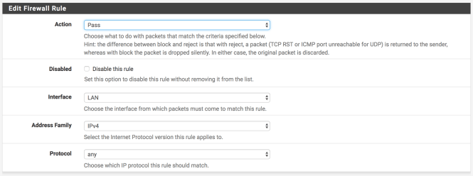
On the screen presented we now need to update the following input fields under Edit Firewall Rules:
- Action should be set to pass
- Interface to LAN
- Address family to IPv4
- Protocol to any
The following screen shot demonstrates what this looks like:
Next we need to make sure under the Source section the value is set to LAN net and under Destination the value is set to any.
The following screen shot demonstrates how the rest of the settings should look:

Save the changes.
You will be returned to the firewall rules, and will see the following message:

Click the Apply Changes button to update the firewall. Once complete you should see a message showing they have been successfully applied.
You should now be able to access the Internet.
In future posts we will look at the rules set in further detail.
Summary
So far we have setup our modem in Bridge Mode and directed traffic to our pfSense firewall. The firewall is now configured to allow traffic to and from the Internet for devices plugged directly into it.
Next in VPNs, firewalls and VLANs for Home Automation – Part 2 we will look at configuring a WAP to allow wireless access for multiple devices to the web. Here we will look at DHCP and ARP in more detail.
In later posts we will convert the WAP over to using a VLAN.
