Raspberry Pi to Arduino shield thermostat – a sneak-peek

Here is a sneak-peek of the Raspberry Pi to Arduino shield based thermostat project I have worked on for the upcoming book.

The prototype you see below is part of a project in one of the chapters:

This uses a relay shield attached to the Raspberry Pi to Arduino shield. The relays are then switched on and off based upon a change in temperature. Connected to the relay shield is a wall powered electric fan.

Enjoy!

A quick update

Just a quick post with some updates:

Commercial Home Automation

There are a number of products out in the market I;d like to give a test run and review here. I’ve listed a couple of these below. Unlike X10 these devices use web based techology.

Iris

Lowes have launched their own home automation tools known as Iris. You can see a variety of the devices here:

http://www.lowes.com/cd_Iris_239939199_

WeMo

Like Lowes Belkin aso have their own home automation devices under the WeMo brand:

http://www.belkin.com/us/wemo

dd-wrt

I’ve been experimenting with dd-wrt using a spare wireless router I have at home. It’s a great piece of software and allows you to turn a second wireless router into a bridge-relay for your existing network. I think I will actually end up using it for creating a second more secure network for running my home automation devices over. I can then use the existing wi-fi network for regular surfing, netflix etc.

http://www.dd-wrt.com/site/index

Gertboard

So after a long wait the Gertboard has finally arrived. It is in kit-form so I’ll be spending some time soldering the components together. Keep your eyes peeled for further updates on this!


Gertboard Kit

Gertboard Kit


Raspberry Pi to Arduino connection bridge experiment – DC Motor

I’ve been doing some experimentation with the Cooking Hack Raspberry Pi to Arduino connection bridge for the upcoming book.

Here is a quick sneak-peak of an experiment I conducted when testing out some of the hardware.

The video below shows a combination of a Raspberry Pi, the Cooking Hacks shield, an Arduino motor-shield  a small DC motor and a circuit consisting of a resistor and photo-resistor.

The software in the background is processing the feedback from the photo-resistor and deciding when to turn the motor on and off, and in which direction. This software also generates the necessary PWM for the motor.

In the video I cover the photo-resistor to turn the motor clockwise and then uncover it to turn it counter-clockwise.

Enjoy!

P.S Thanks to Andy C on the Cooking Hacks forum for pointing me in the direction of using C threads for PWM.

Thermostats Part 4 – Ethernet thermostat screen review

Screen comparison

In this post I am going to be briefly reviewing a variety of screen types for my thermostat and deciding upon which will fit the bill for the Ethernet model I am building.

The three screens I have in my collection are:

1.) 2.8″ TFT Touch Shield for Arduino – 2.8″ 

2.) Adafruit 1.8″ 18-bit Color TFT Shield w/microSD and Joystick

3.) 16×2 LCD screen

You can see the three screens side by side below:

Comparison of screen types

Comparison of screen types

Lets start by looking at the 2.8″ TFT touch screen.

2.8″ TFT touch screen

This device is an Arduino shield and a very nice one at that. It plugs straight into the top of your board ( I have been using an Uno) and there are some libraries available from the Adafruit site to start testig it out.

The screen is large and easy to use which is nice, and the picture quality is good. Being touch screen it also has the benefit that I wouldn’t need to use buttons on my thermostat as manual override/control could be performed directly on the screen.

Touch screen shield

Touch screen shield

The down side to the shield though is that it is very greedy when it comes to pin use.

I tried wiring up my all in one thermistor/resistor unit to the Arduino, plugged in my Ethernet shield with the screen and hit some problems. When the shield initializes it uses some of the pins that the Ethernet shield uses, and vice versa.

At this point I hadn’t tried to hook up any relays which I will also need to switch the mains power on and off to the baseboard heater. The screen may work with some modifications but considering I have other options I will hang on to it for now and use it in another part of the system.

I suspect this shield will be better placed on a wireless thermostat device that uses a Xbee radio for communication, although I will have to do some more experimentation here.

So all in all it is a great shield but isn’t right for the particular style of thermostat I am building at the moment.

1.8″ TFT shield  

The next option was the TFT shield that comes complete with a miniature joystick and SD card reader.

This is a neat little device that requires minimal soldering (just some headers) and then acts as an Arduino shield. It has a nice screen and the added bonus of an SD card slot for loading up images to the device. The Arduino pins can be accessed along the top of the board so unused pins can still be used.

1.8" screen

1.8″ screen

I like this shield a lot, although I have some concerns about whether the joystick-button combo is right for the thermostat. Ideally I would like a few buttons that are always visible. With the previous TFT shield I could literally draw the buttons out and display them at the base of the screen at all times.

With this device, whilst this is possible, to navigate between the options would require using the joystick which may be awkward depending on the angle of the thermostat on the wall. I also feel as if the SD card slot would be wasted on this project as the thermostat has no use for it.

Having done some experimentation with it I decided against using this device for this particular thermostat and will hold onto to it until I can find a project that requires a screen + SD card reader.

16×2 LCD screen

My final option is the LCD screen. This certainly doesn’t have the polish that using one of the top two devices has and lacks the richness in GUI options.

On the plus side it is small allowing space for extra buttons and uses a minimal number of pins. Also not being a shield allows me to hook this up onto a proto-board along with a relay and the thermistor reducing the stacking of components and making my device slimmer. I could get away with just three boards, the Uno, the Ethernet and the Proto.

LCD screen

LCD screen

What I will loose in visual polish I will make up for size. This seems like a fair trade off.

Having played around with the screen I think I can make this work and will use it for the Ethernet thermostat.

This just leaves me with designing a proto-board that contains the screen and other components. For $16 I can get a Makershield from Makeshed and solder my devices to it easily.

So all-in-all this seems like the best path forward.

Conclusion

The LCD device while not the best looking will do the job. My next post on the Ethernet thermostat will look at starting the construction process and review all the components necessary. I’ll also be showing some experimentations I have done with a relay shield and mains power.

The past few weeks have seen some experimenting with the Arduino-to-Raspberry Pi shield so expect a post on that soon, as a heads up it is very cool!

A quick update

Time has been a little tight this past few weeks due to the book and a high work load.

However this week I will be catching up on my blogging. Expect a post comparing screen types for the Arduino!

Raspberry Pi to Arduino Bridge

I came across this neat little board the other day:

http://www.cooking-hacks.com/index.php/raspberry-pi-to-arduino-shield-connection-bridge.html

The Bridge looks like an Arduino shield and connects to the GPIO pins on your Raspberry Pi. After setting up the software you can then hook up Arduino shields to your RPi.

This obviously opens up all sort sof possibilities as there are an array of Arduino shields out there that are capable of some great functionality.

This is also open up the Raspberry Pi for building sensor projects, something I will be exploring in latest posts.

Hurricane Sandy

Introduction

This post will start of with a live blog of the current power situation due to the hurricane. After this I’ll be concluding the post with an overview of the utility and power line situation is Connecticut.

Live Blog

Providing live blogs when possible of the current situation here:

2:15 pm Monday – I was working from home today. Our office was shutting down at 1pm and it was safer to work from home and avoid the roads. At around 2:15 the power went out . We will shortly be cranking up the generator. Currently posting from iPhone while G3 is still available.

7:05pm Monday – Our power came back on again around 4:30. It has gone out then come back on again twice. It’s now dark and from what we can see, one tree has split in two in the back yard (thankfully it turned out to just be a large tree limb), and the garden shed is wrecked.

8:16pm Monday – We’ve had a fire truck on the street visiting one of the houses, hopefully it was nothing serious. Plenty of debris flying about including numerous signs from people yards for election candidates.

One of neighbors cars has had a basketball net that was cemented into the ground land on it.

10:15pm Monday – The power has gone out again.

Tuesday Morning– The worst of the weather is gone now. Taking a drive we can see power lines and trees down all over the place. The snow storm last year seems to have taken out a lot of the dead trees, so it could have been lot worst. Compared to New York, New Jersey and Long Island sound  we have gotten off very very lightly.

Damaged Tree Line

Damaged Tree Line

McDonalds appears to be the only place open.

Tuesday Afternoon – No power all day. I spent some of the day moving location trying to find an Internet connection. Went to my in-laws business and we had power for most of the morning, then around 1:30 it cut out.

Eventually made it via detours to the office for a couple of hours.

Cleaned up a lot of the debris in the garden and managed to jam the shed doors back on. Time for a new shed though.

Found door number 1

Found door number 1

The lawn guy is going to come and take care of the tree.

Broken Tree Limb

Broken Tree Limb

Thankfully garbage collection is coming Wednesday so we threw out some of the food from the refrigerator.

Tuesday Evening – Still no power. We have now cranked up he generator and are running some of the house off of it. A few places are open for food so we are going to heat out.

Finished a chapter of the ook but can’t submit it via email until the morning.

Hoping for power back on Wednesday

Wednesday  8am – Power is still out. Checking the utility company’s website I can see that 35% of the town are still down. Hopefully they can resolve this today.

Thursday Evening  – We got a our power back on finally Thursday evening. The lawn guy is coming Saturday to take down the dead tree and remove the branch.

Conclusion

Parts of Connecticut really got hit badly by the storm (the coast), but I think overall as a state inland we got off very lightly.

The CT Air National Guard released this video of the coast line which shows the severity:

It looks like the power companies will have most people (around 98%) back up with power by the end of day tomorrow.

I’m sure the question is going to be asked about why cables aren’t being run underground and how the grid can be made more resilient to storms.

I’m also going to be looking into the pros and cons of a solar system to act as a backup for black outs – this is the third major storm we have had since August last year where we have had power knocked out for days on end.

EEG Headsets

Just a quick post on something worth checking out.

Canadian Tech company InteraXon will be releasing their EEG powered headset called Muse next year. You can read more about the device here.

They are currently raising funds from the tech community via IndieGoGo. The process basically involves making a pledge of a certain amount of dollars up front, in return for a Muse headset after the first production run.

More details can be found on the funding section of their website here

To quote from the indieGoGo crowdfunding website:

Introducing Muse, our brainwave-sensing headband.

It’s a comfortable, sleek, four-sensor headband that allows you to control applications, games, reduce stress, improve memory and concentration, and eventually control devices directly with your mind.

Muse measures your brainwaves in real-time. It sends those brainwaves to your smart phone or tablet showing you how well your brain is performing and also translates your brainwaves into instructions to interact with content on your iOS or Android device.


This device obviously offers some excellent opportunities for home automation, a post will be in the works exploring some possibilities.

In the meantime check out their promo video:

Thermostats – Part 3 – The Ethernet Model prototyping

Introduction

As part of my heating system I have discussed how I am building a set of thermostats that can control the baseboard heaters in my house. The vast majority of these heaters are not located near my PC, electrical box or any of my other computer hardware.

However there is one, that is located in my office close enough to my router that I can connect it up via Ethernet rather than WiFi.

This post will begin looking at prototyping the Ethernet model. A prototype is a handy way of testing the components we have purchased and experimenting with the equipment before we solder it together.

Components required

For the Ethernet model of the thermostat the following components are required:

  1. Arduino Uno
  2. Temeprature sensor
  3. Visual display unit
  4. Ethernet shield
  5. Buttons/manual method of input
  6. Power supply
  7. Ethernet cable
  8. Relays

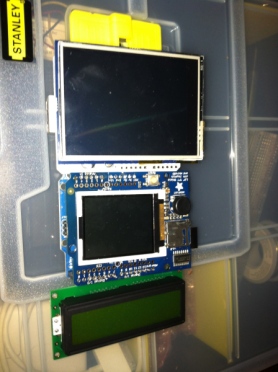
The picture below shows a group of components I purchased to build the Ethernet model and to prototype with. It includes:

  1. An Arduino Uno
  2. Seeed Studio Ethernet Shield
  3. Temperature sensor purchased from Adafuit – AM2302
  4. All in one TFT screen + button joystick – 1.8″ TFT
Thermostat components

Thermostat components

First steps are prototyping

The prototype we will be exploring below will build a simple thermometer.

For the prototyping I will not  be using the TFT Shield to start with. This is primarily because I am evaluating screen types, which are the best and which ones are better suited for certain locations in the house.

There is a separate post in the works for this, and the outcome of that evaluation will result in the chosen screen type when I blog about turning the Ethernet prototype into the production model.

So to start with we will hook up Arduino, Ethernet shield and temperature sensor and test it works.

For the temperature sensor there is code available via the Adafruit site for testing purposes. This can be downloaded here, along with the instructions for wiring up your equipment.

The picture below shows the temperature sensor wired up.

Temperature sensor

Temperature sensor

Once the sensor was wired up I tried out a few of the test sketches that could be downloaded from the above link. Once I was happy this worked, I then attached the Ethernet shield to the Arduino and attached the temperature sensor to the Ethernet shield.

The picture below shows this setup. Note: At this point I haven’t done any soldering.

Ethernet shield

Ethernet shield

File->Examples->Ethernet->Web server

example.

Modify the settings in the code to assign it an IP# for your local network and upload it to your Arduino. Once done, you can plug in the Ethernet shield to your router and access the IP# you assigned it via a browser on a home computer or tablet.

If you receive the “analog input” message on your screen as a web page, your test has been successful.

For our next test we are going to merge some of the code from the web server example and the temperature example that you downloaded from the Adafruit website.

First, attach your Arduino back to your PC if it isn’t already setup.

Ethernet and Thermostat

Ethernet and Thermostat

Take the following test code and paste it into the Arduino IDE.

Test code.

/*
 Web Server

 A simple web server that shows the value of the analog input pins.
 using an Arduino Wiznet Ethernet shield. 

 Circuit:
 * Ethernet shield attached to pins 10, 11, 12, 13
 * Analog inputs attached to pins A0 through A5 (optional)

 created 18 Dec 2009
 by David A. Mellis
 modified 4 Sep 2010
 by Tom Igoe
 modified 18 Oct 2012
 by Andy Dennis

 DHT test

 Returns temperature and humidity.

 modified 18 Oct 2012
 by Andy Dennis  

 */
#include "DHT.h"
#include <spi.h>
#include <ethernet.h>
#define DHTPIN 2 // what pin we're connected to
#define DHTTYPE DHT22 // DHT 22 (AM2302)
// Enter a MAC address and IP address for your controller below.
// The IP address will be dependent on your local network:
byte mac[] = { 0xDE, 0xAD, 0xBE, 0xEF, 0xFE, 0xED };
IPAddress ip(192,168,1, 177);
DHT dht(DHTPIN, DHTTYPE);
// Initialize the Ethernet server library
// with the IP address and port you want to use 
// (port 80 is default for HTTP):
EthernetServer server(80);
void setup()
{
  // start the Ethernet connection and the server:
  Ethernet.begin(mac, ip);
  server.begin(); 
  dht.begin();
}
void loop()
{
  float h = dht.readHumidity();
  float t = dht.readTemperature();

  // listen for incoming clients
  EthernetClient client = server.available();
  if (client) {
   // an http request ends with a blank line
   boolean currentLineIsBlank = true;
   while (client.connected()) {
     if (client.available()) {
       char c = client.read();
      // if you've gotten to the end of the line (received a newline
      // character) and the line is blank, the http request has ended,
      // so you can send a reply
      if (c == '\n' && currentLineIsBlank) {
        // send a standard http response header
        client.println("HTTP/1.1 200 OK");
        client.println("Content-Type: text/html");
        client.println();

        // check if returns are valid, if they are NaN (not a number) then something went wrong!
        if (isnan(t) || isnan(h)) {
        client.println("Failed to read from DHT");
     } else {
        client.print("Humidity: "); 
        client.print(h);
        client.print(" %\t");
        client.print("Temperature: "); 
        client.print(t);
        client.println(" *C");
     }

     break;
   }
   if (c == '\n') {
     // you're starting a new line
     currentLineIsBlank = true;
   } 
   else if (c != '\r') {
     // you've gotten a character on the current line
     currentLineIsBlank = false;
   }
  }
 }
 // give the web browser time to receive the data
 delay(1);
 // close the connection:
 client.stop();
 }
}

The above code is simply a combination on the Web server sketch and DHTester sketch combined.

You can modify the IP# on this to assign it one on your home network and change the output message if you like.

Now upload this to your Arduino and hook it back up to your router.

With your PC/Tablet, now hit the IP# you assigned it via your web browser. You should see something like the following (provided you didn’t modify the message)

Humidity: 52.3% Temperature: 26 C

This confirms that the temperature sensor is working, and the data can be output via HTTP over Ethernet.

Next Steps

Obviously this is a very simple example, and doesn’t do what we need it to yet. However it demonstrates some of the technologies we plan to use, and also confirms that our components are working. We also have a working thermometer as a by-product of our tests.

Our next steps will be as follows:

1.) Choose the correct VDU (visual display unit)

2.) Test the VDU alongside the prototype code

3.) Write the code to output the temperature over HTTP and to send the data back to the Raspberry Pi

4.) Write the code to manipulate the baseboard heaters

5.) Solder the components together

6.) Place them in a case

7.) Wire the new thermostat unit into the baseboard heater, and attach it to the wall.

I’ll be blogging on the above to provide an easy guide to completing the production model, and also adding the code to BitBucket.

Summary

The above example has shown that a quick prototype can be used to test our components before writing a lot of code and soldering equipment together.

The next post in this series will be dedicated to testing the VDU and assigning one to the prototype that is easy to use and displays the data we need it to.

A quick update

This month has been extremely busy so time for blogging has been tight.

Here is a quick update of what is going on with the heating and associated projects:

Book deal

There is now currently a book in the works covering some of the topics on this website using a new technology available for the raspberry Pi. I won’t give too much away in this post, other than to say, if you are interested in the subjects blogged about here, then this is a book for you. More details on this as I can release them.

Change in temperature

As October has rolled in, the temperature has started to drop. This is perfect timing for testing one of my first thermostats – the thernet model. More on this thermostat in a separate post to follow

Database server

Over the next couple of months I will be sourcing the hardware to set up my permanent Postgres DB server. If you followed my earlier post on the prototype DB server I showed how we can set up a Postgres DB for storing temperature readings and then query it with HTSQL. Going forward I will document the setting up process of the actual production server, the database architecture and HTSQL server configuration. All of code will be available via BitBucket which leads me too….

BitBucket account

I will be setting up a BitBucket account where you can download copies of the bash scripts, code and documentation for your own projects.

Index/ToC page for the blog

Expect to see an Index/ToC page for the blog. This will provide a page where posts are grouped by topic and thread, so you can read a set of posts on a particular subject in logical order when working on that aspect of your heating system.

Other subjects

There are some posts in line discussing:

  • MagPi – the Raspberry Pi fanzine
  • Arduino visual display components – a comparison of TFT and LCD components for thermostats
  • Some good books worth reading
  • X10 – A look at the X10 standard, thanks to stillwaternc for the discussion on this over on the About page.

So keep your eyes on this space for more posts to come.